SCI Prophet VS NEW PSU
About Sequential Circuits SCI Prophet VS PSU (power supply) replacement
This modern and state of art PSU is suitable to replace an old PSU in Prophet VS synthesizer. It is an universal input (85 to 265V AC) switch mode power supply (SMPS).
In comparison to original PSU it has several advantages
- NO OVERHEAT! Original transformer and aluminium heat sink become hot after several hours of operation. In this PSU, power components are 25°C warmer than the ambient temperature (e.g. for ambient +20°C it is +45°C)
- Efficiency around 77{eb681a58ecc476759952a50a8a7c167279151df38e58f2598760f2d2e5f4f286} (vs. 30{eb681a58ecc476759952a50a8a7c167279151df38e58f2598760f2d2e5f4f286} in old PSU) = less heat inside the synthesizer
- NOISE FREE: get rid of buzzing of the old transformer
- Precise Over Voltage and Over Current Module that monitors possible fault conditions
- Weight 270 g vs. 1020 g
- New and quality electronic parts
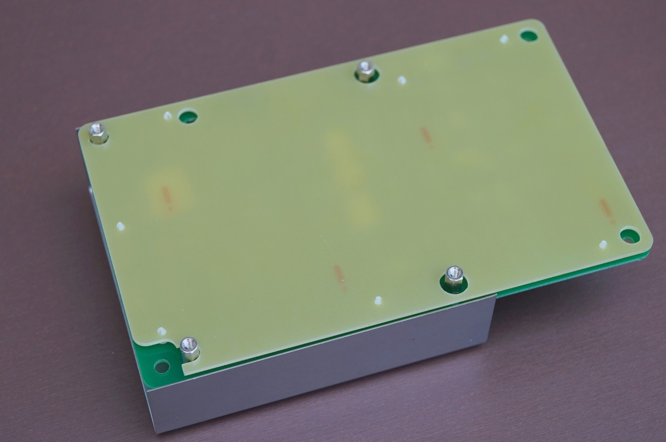
- Top metal protection plate and bottom insulator plate that covers all components under high voltage
- Compact construction
- Easy to install
- For sale Complete PSU module incl. insulator board and protection metal cover + all necessary parts to install the PSU
- Price: 250€ net


Technical information
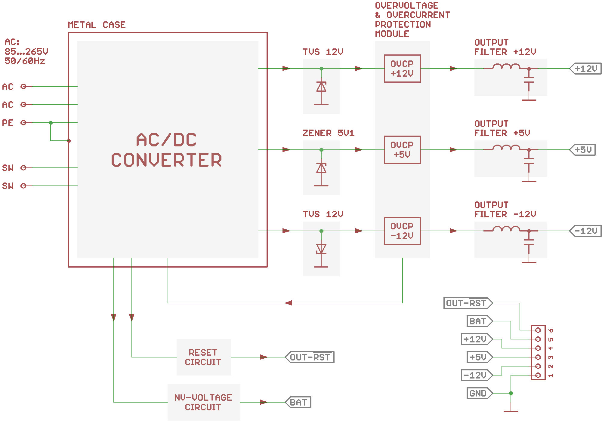
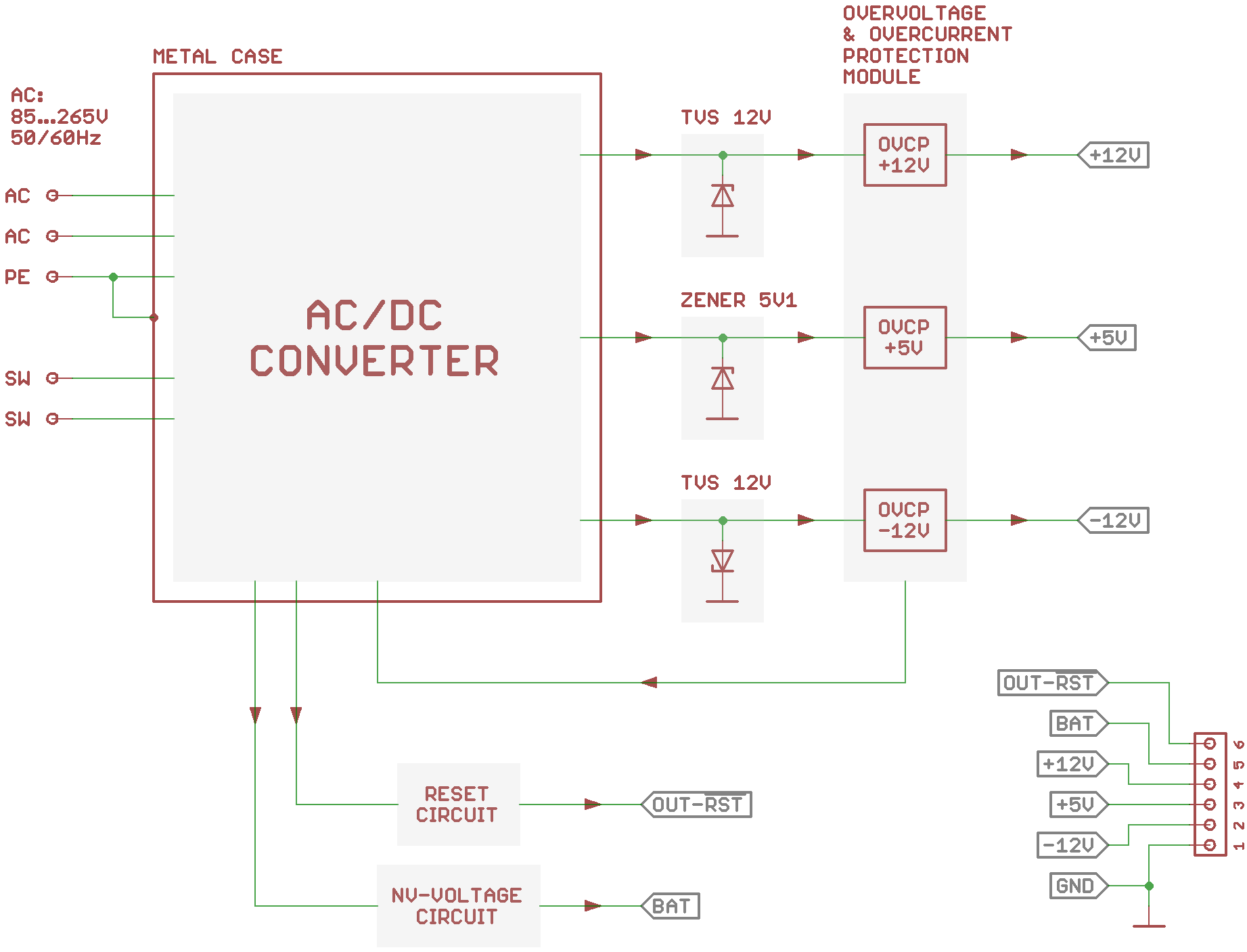
Below block diagram of PSU is depicted. It consists of AC/DC converter, Zener Diode (ZD) / Transient Voltage Suppressors (TVS), Overvoltage and Overcurrent Protection Module, Reset Circuit and NV-Voltage Circuit.
AC/DC converter
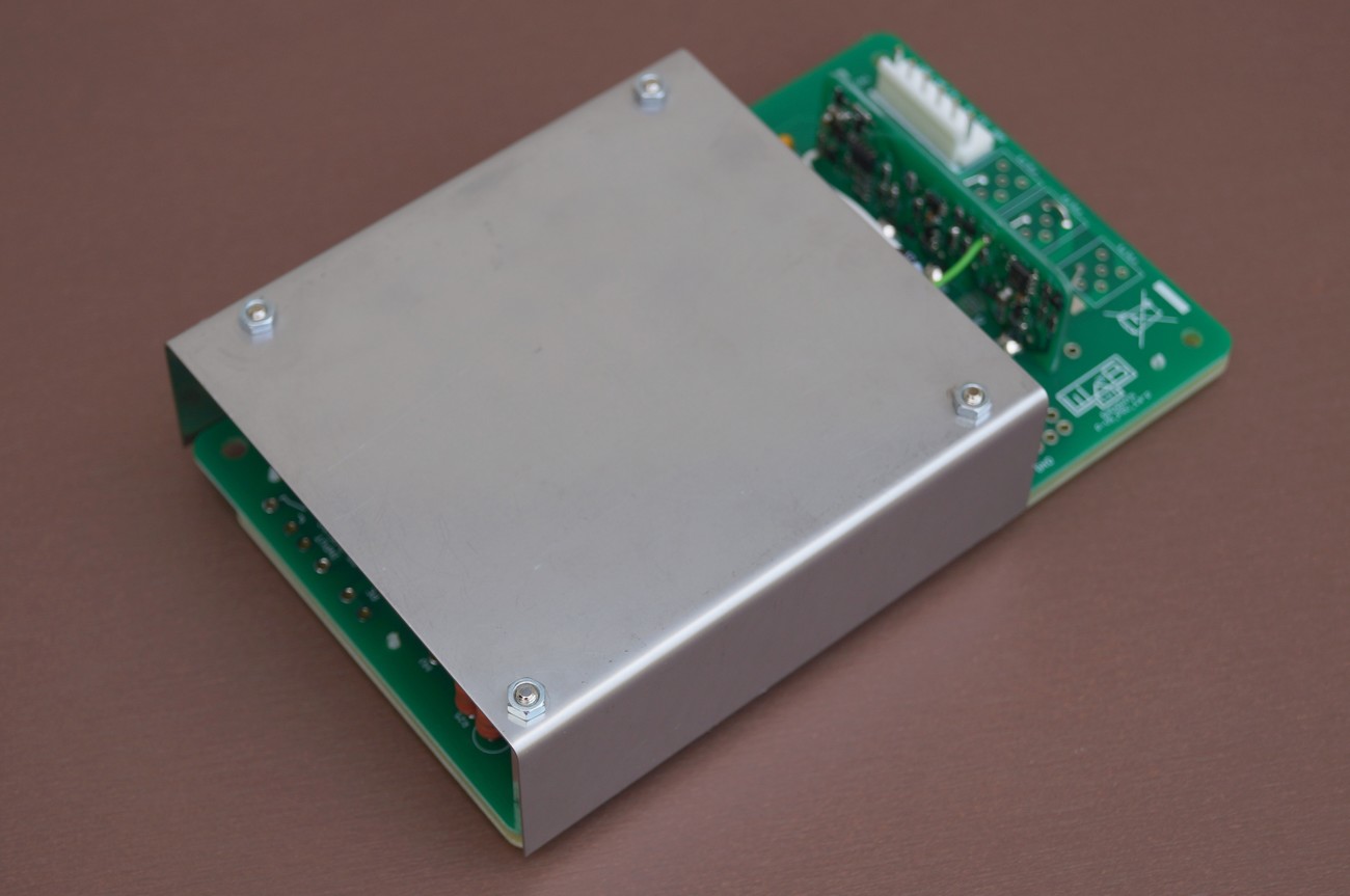
The converter has a universal 85…265VAC 50/60Hz input. It has internal over-load/temperature protection. If over-load/temperature event occurs, the AC/DC converter turns off (to be precise, the power stage turns off; the converter is still powered with a line voltage). The red LED (in the left down corner in pictures above) will start to lit. Disconnecting (for approx. 10s) of the converter from the line voltage will reset the PSU and if no fault condition is present it will start to work normally.
AC/DC converter uses multiple output flyback topology and the +5V rail should be always loaded with at least 200mA. To avoid useless losses in the converter, there is no internal pre-load resistor inside (as it is usual for normal multi output PSUs on the market), so be sure +5V rail is connected to the synth circuitry. At the same time +-12V rails should be also connected to the synth circuitry.
Zener Diode (ZD) / Transient Voltage Suppressors (TVS)
These diodes clamp the overvoltage on +5V and +-12V rail. Clamping voltage is +5,1V and +-13V respectively
Overvoltage and Overcurrent Protection (OVCP) Module
Overvoltage and Overcurrent Protection Module has precise voltage and current sensors for every rail. OVCP module is connected to the AC/DC converter controller IC. If any of following events occurs, the AC/DC converter will latch off (as described above in the „AC/DC converter“ part):
- Voltage on +5V rail raises to +5,4V
- Voltage on +12V rail raises to +13,0V
- Voltage on -12V rail raises to -13,0V
- Current on +5V rail raises to 1,25A (normal Prophet VS +5V rail consumption is 0,8A without cartridge)
- Current on +12V rail raises to 0,58A (normal Prophet VS +12V rail consumption is 0,3A without cartridge)
- Current on -12V rail raises to 0,58A (normal Prophet VS -12V rail consumption is 0,35A without cartridge)
Reset Circuit
Produces reset signal for digital circuitry.
There is 300 mVpp line frequency ripple on the reset rail in the original PSU. This new PSU eliminates this ripple
NV-Voltage Circuit
Supplies NV-RAM when Prophet VS is turned on.
As conclusion, this PSU has superior protection against fault conditions:
Triple OVP protection:
- precise voltage sensors as a part of OVCP module
- clamping with 5V1 and 12V TVS diodes
- controller IC OVP circuit
Double overcurrent protection:
- coarse over-current and short circuit protection as a part of controller IC circuit
- precise current sensors as a part of OVCP module
d
d
Installation instructions
PLEASE NOTE! We sell a fully working and tested PSU with few additional parts to mount the PSU into the Prophet VS. The following installation is an example. We are not responsible for health injuries and material damages that can cause bad installation of this PSU. Only a qualified tech should make this PSU swap. You are doing the PSU swap on your own risk.
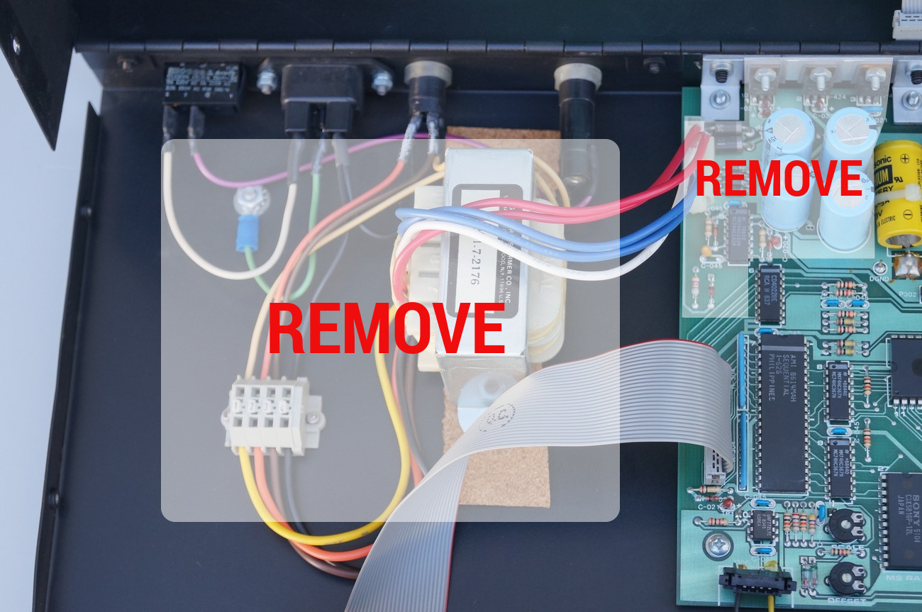
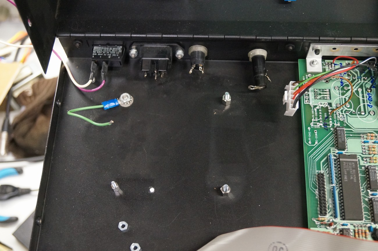
Remove all PSU-related parts as marked above. Don’t remove one diode (see next figure)
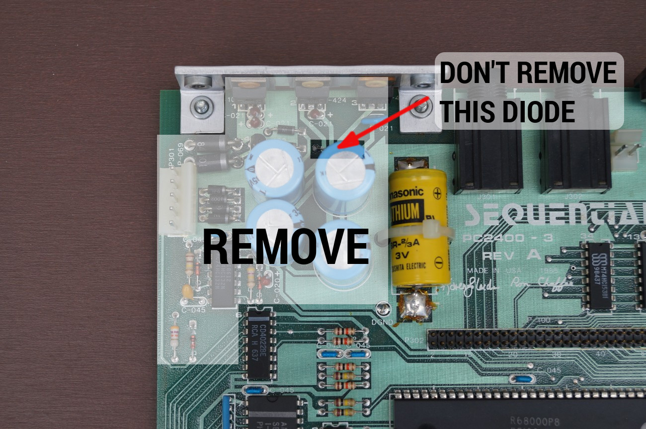
Don’t remove this diode
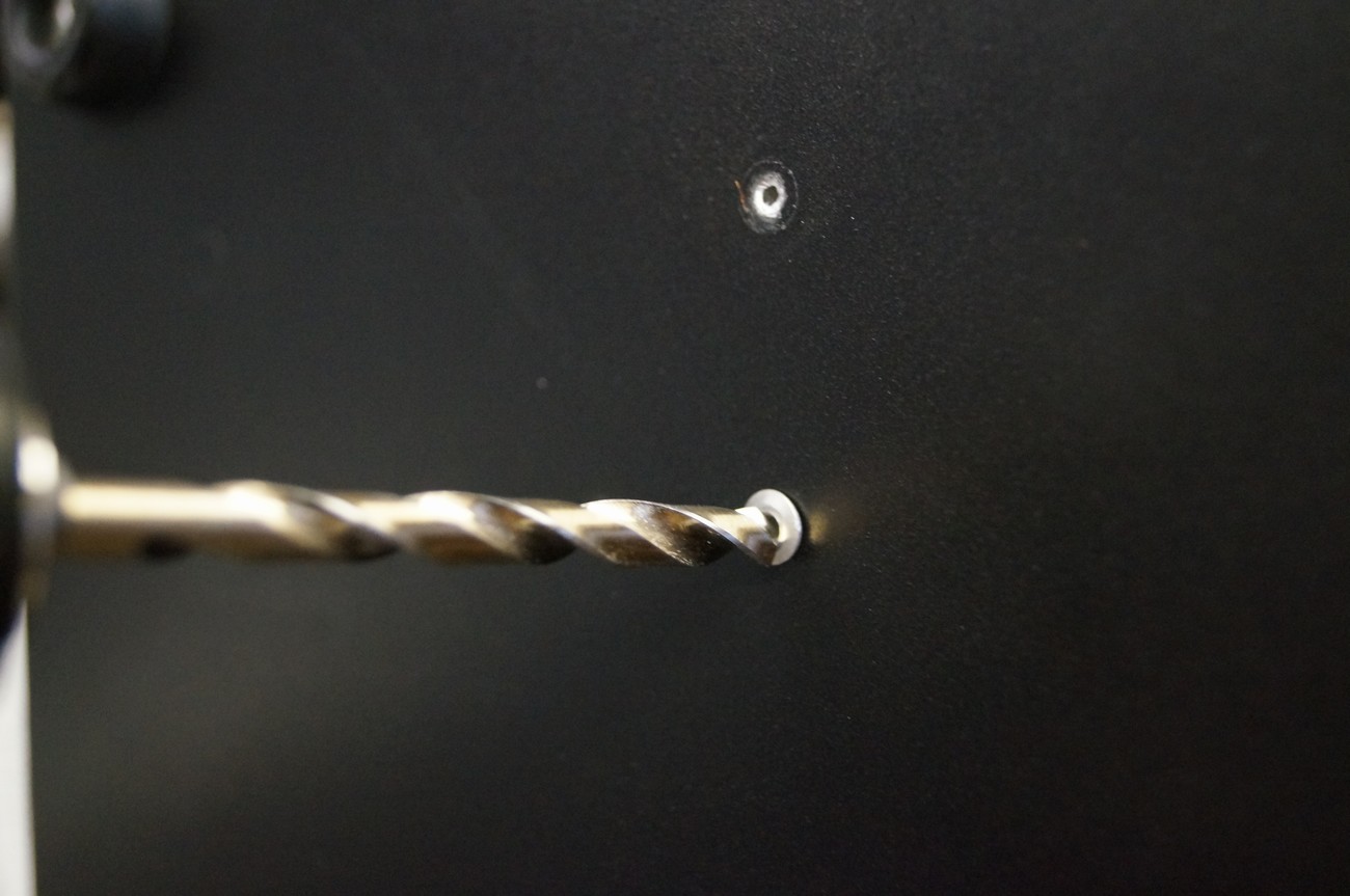
Use 4mm drill to remove 2x rivets that are holding cable strip (yellow, orange, brown, black wires are connected together by means of this part)
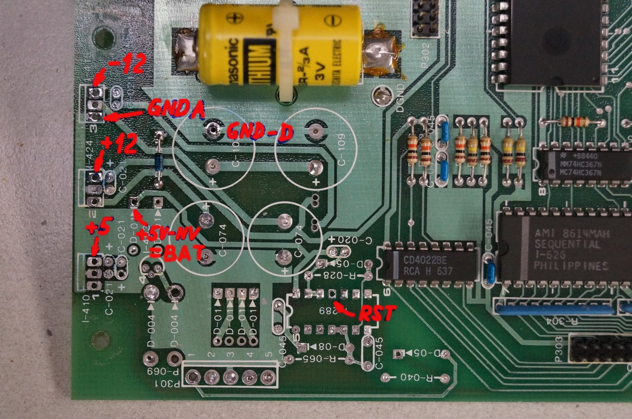
Now the PCB should look like this. Mark the necessary pads to solder the wires that will be connected to PSU
Fasten 3x 8mm spacers (female) by means of 3x M3x16 screws. Put the PSU on them – it should fit
Before putting the PSU PCB inside the synth unscrew at first the fuse holder and move it in direction out of the synth.
Mount insulator plate onto the PSU board (if not already mounted). Use small snap in plastic spacers
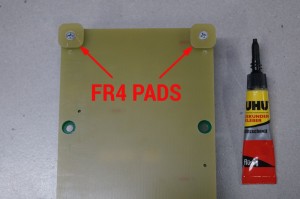
Mount 2x 8mm spacers (male + female) with FR4 pads onto the PSU board
Put a proper amount of the instant adhesive onto the FR4 pads
Now, place the PSU into the synth on the 3x already mounted spacers and press the two FR4 pads onto the metal case and wait until the adhesive will stick
Now, all 5 spacers are fastened to the metal chassis of the synth
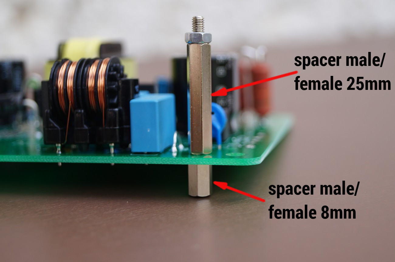
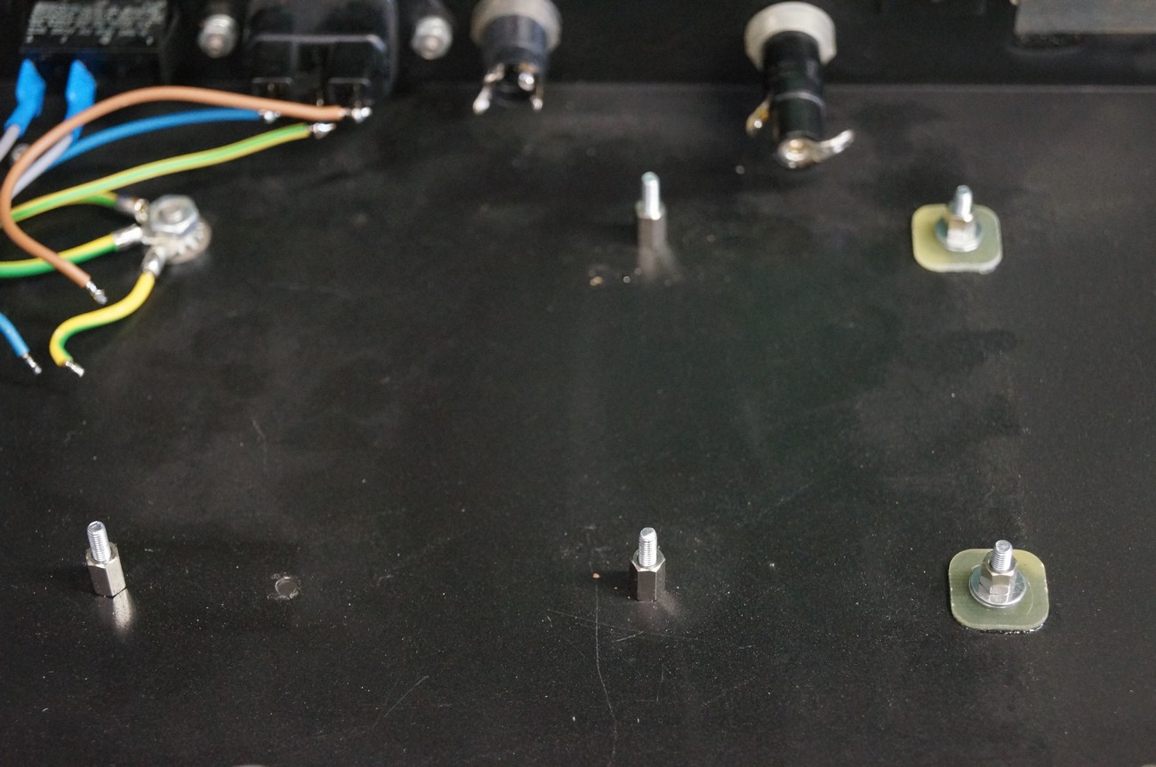
Install 8 and 25 mm spacers as depicted. Note: The bottom 8mm spacer is not screwed to the metal case

Solder cables to the mains socket as depicted
Install earth cables as depicted
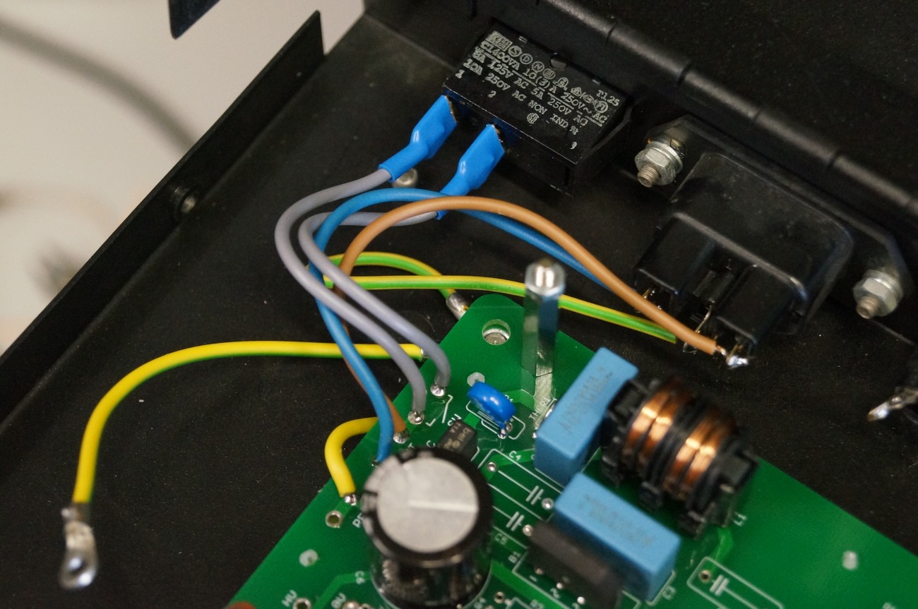
Solder cables to the switch as depicted
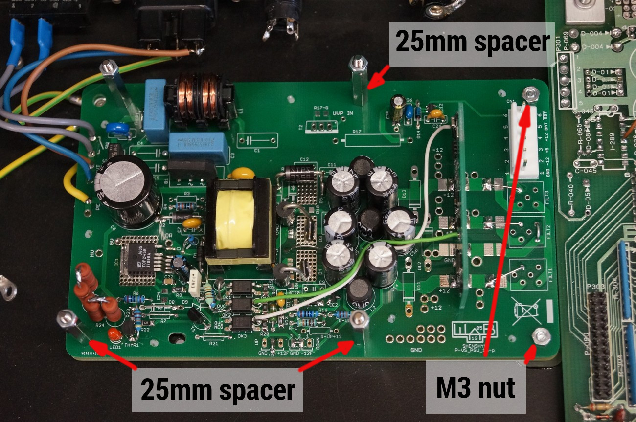
Place the PSU onto already installed spacers and fasten as depicted above
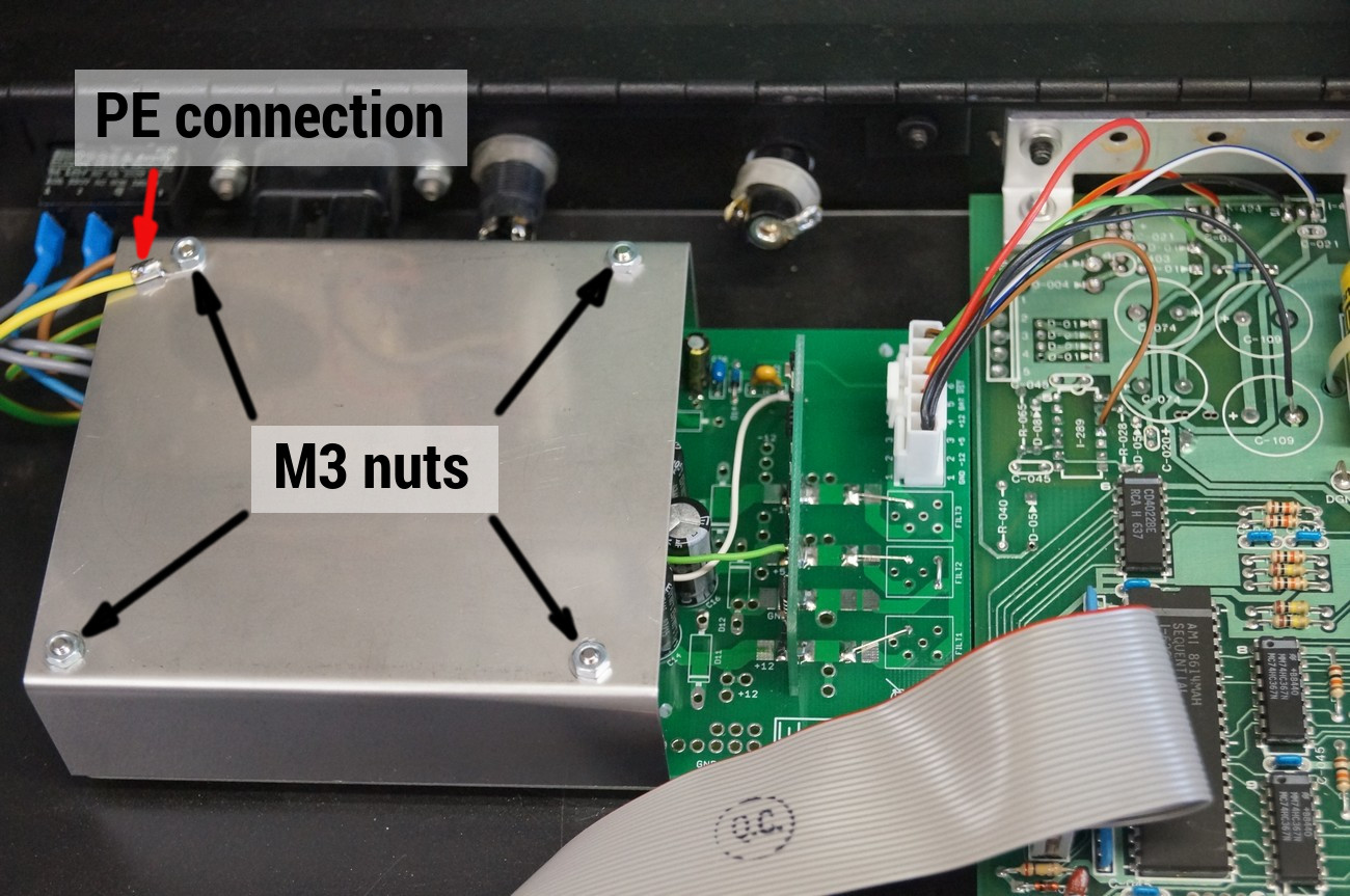
Put the metal case on the top and fasted with nuts. Don’t forget to fasten the earth cable to the metal case

Mark the rear side of synth with stickers as depicted
DOUBLE CHECK EVERYTHING!
Connect 6 ohm / 4 W resistor between +5 V rail and ground.
Connect 40 ohm / 4 W resistor between +12 V rail and ground.
Connect 40 ohm / 4 W resistor between -12 V rail and ground.
Turn on the PSU and check the unit is working properly and all voltages are present (+12V, +5V, -12V)
Plug the six pole connector into the PSU module
READY!