Matrix 1000 PSU replacement
About Oberheim Matrix 1000 (power supply) replacement
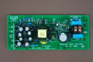
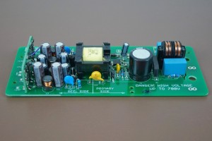
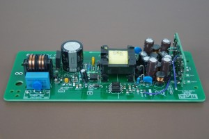
This modern and state of art PSU is suitable to replace an old PSU in Oberheim Matrix 1000 synthesizer. It is an universal input (85 to 265V AC) switch mode power supply (SMPS) with LDO post-regulators (on every rail). The PSU has an open frame design.
In comparison to original PSU it has several advantages
- NO OVERHEAT! In this PSU, power components are only 15°C warmer than the ambient temperature (e.g. for ambient +20°C it is +35°C) after several hours of operation
- Efficiency around 75{eb681a58ecc476759952a50a8a7c167279151df38e58f2598760f2d2e5f4f286} = less heat inside the synthesizer
- No audible NOISE or HUM
- Precise Over Current Module that monitors possible fault conditions
- Less weight
- New and quality electronic parts
- Bottom insulator plate that covers all components under high voltage
- Compact construction
- Easy to install (not necessary to bore extra holes in the chassis)
- For sale complete PSU module incl. insulator board + all necessary parts to install the PSU
- Price: 190€ net
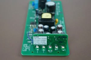
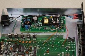
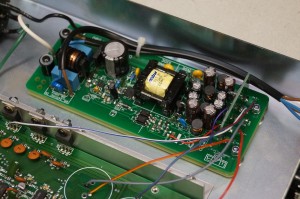
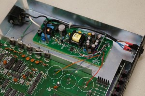
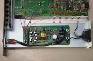
Matrix 1000 PSU replacement module
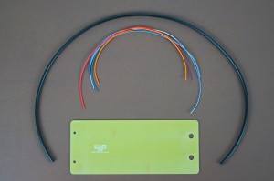
Cables and insulator plate
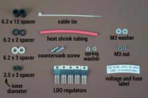
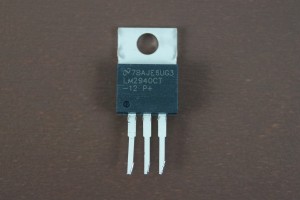
Aux parts and LDO regulators
Technical information
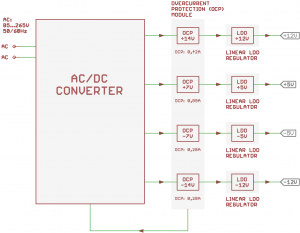
Below block diagram of PSU is depicted. It consists of AC/DC converter, Overcurrent Protection (OCP) Module and LDO regulators
AC/DC converter
The converter has an universal 85…265VAC 50/60Hz input. It has internal over-load/temperature protection. If over-load/temperature event occurs, the AC/DC converter latches off (to be precise, it stops to switch and produce output voltages; the converter primary high voltage stage is still powered with a line voltage). Disconnecting of the PSU from the line voltage will reset the converter and if no fault condition is present it will start to work normally.
AC/DC converter uses multiple output flyback topology. The feedback senses +7 and -14 rails. Output voltages are approx. +14V (-1V/+2V), +7V (-1V/+1), -7V (-1V/+1V), -14V (-1V/+2V) that are further regulated by LDO regulators.
Overcurrent Protection (OCP) Module
Overcurrent Protection Module has precise current sensors for every rail. OCP module output is connected to the AC/DC converter controller IC. If any of following events occurs, the AC/DC converter will latch off (as described above in the „AC/DC converter“ part):
- Current on +12V rail raises to 0,42A (normal Polysix +12V rail consumption is 0,14A)
- Current on +5V rail raises to 0,89A (normal Polysix +5V rail consumption is 0,39A for both 5V regulators)
- Current on -5V rail raises to 0,28A (normal Polysix -5V rail consumption is 0,09A)
- Current on -12V rail raises to 0,28A (normal Polysix -12V rail consumption is 0,12A)
Current sensors have tolerances +-2{eb681a58ecc476759952a50a8a7c167279151df38e58f2598760f2d2e5f4f286}
Linear LDO regulators
LDO regulators in every rail regulate the AC/DC output voltages to +12, +5, – 5, -12V.
As conclusion, this PSU has superior protection against fault conditions:
Dual OVP protection:
- LDOs in series
- controller IC OVP circuit
Double overcurrent protection:
- coarse over-current and short circuit protection as a part of controller IC circuit
- precise current sensors as a part of OCP module
Installation instructions
PLEASE NOTE! We sell a fully working and tested PSU with few additional parts to mount the PSU into the Polysix. Following installation is an example. We are not responsible for health injuries and material damages that can cause bad installation of this PSU. Only a qualified tech should make this PSU swap. You are doing the PSU swap on your own risk
DISCONNECT POWER CORD FROM THE MAINS PLUG
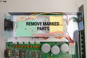
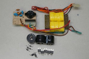
Remove old PSU parts: 5x regulators, 6x diode, 3x bulk caps, transformer and filter PCB
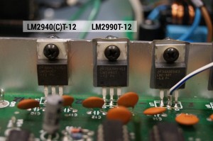
Install new regulators instead of old ones. Use original heat sinks insulators. They should be NOT damaged! If they will be damaged, buy a replacement
Note: to achieve high efficiency of linear regulation, LDO regulators are used instead of standard 78xx/79xx
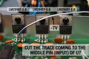
Cut the trace coming to the middle pin of U7 [very important!]
Solder white-blue wire to the middle pin of U7 (LM2990-5)
When installing new LDO regulators, cut pins as depicted. Original pad holes may be pretty tight.
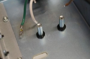
Install 6.2 x 2 spacers as depicted
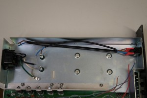
Install cables and use heat shrink for insulation
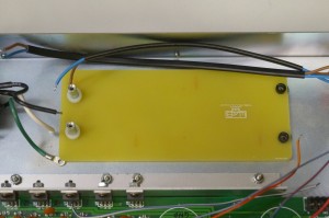
Install insulator plate. Place 6.2 x 3 spacers on one side and 3.5 x 3 spacers on the other side
Put the PSU PCB on the insulator PCB
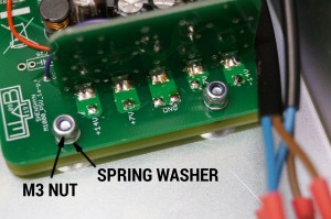
Fix the PCB with countersunk screws, spring washers and M3 nuts on one side
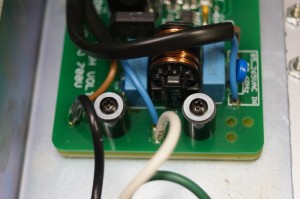
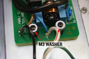
Fix the PCB with 6.2 x 12 spacers, original inch screws and M3 washers on the other side
Solder VAC input wires as depicted
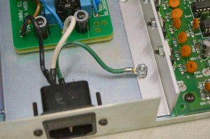
Connect earth cable to the chassis using original nut (inch thread) or use an extra nut if available
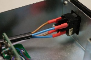
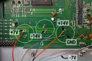
Wire as depicted
Use cable tie to tie both AC cables going to the switch
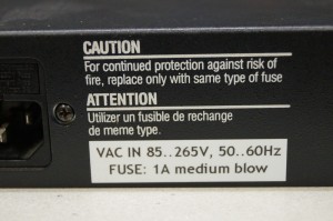
Mark universal input with a label. Cover original voltage rating to avoid confusion
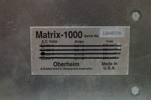
Cross out every voltage rating on the original voltage label to avoid confusion. Now, all voltage are permissible
READY!
Some safety recommendations when working with the PSU
- Be careful, the big bulk electrolytic cap is still charged with high voltage (for 115VAC it is 165V and for 230VAC it is 330V) after the PSU was turned or latched off
- When de-installing the PSU, short + and – terminals of the bulk cap (bottom side of the PCB) with a 470 ohm / 5W resistor for 1 second. At this time, PSU should be disconnected from the line voltage
- Line voltages in the Matrix 1000 are still present, even if switch is turned off! Be careful with line wires!
