Roland Jupiter 8 NEW PSU
About Roland Jupiter 8 PSU (power supply) replacement
This modern and state of art PSU is suitable to replace an old PSU in Roland Jupiter 8 synthesizer. It is an universal input (85 to 265V AC) switch mode power supply (SMPS).
In comparison to original PSU it has several advantages
- NO OVERHEAT! In this PSU, power components are 25°C warmer than the ambient temperature (e.g. for ambient +20°C it is +45°C)
- Efficiency around 75{eb681a58ecc476759952a50a8a7c167279151df38e58f2598760f2d2e5f4f286} = less heat inside the synthesizer
- No audible NOISE
- Precise Over Voltage and Over Current Module that monitors possible fault conditions
- Less weight
- New and quality electronic parts
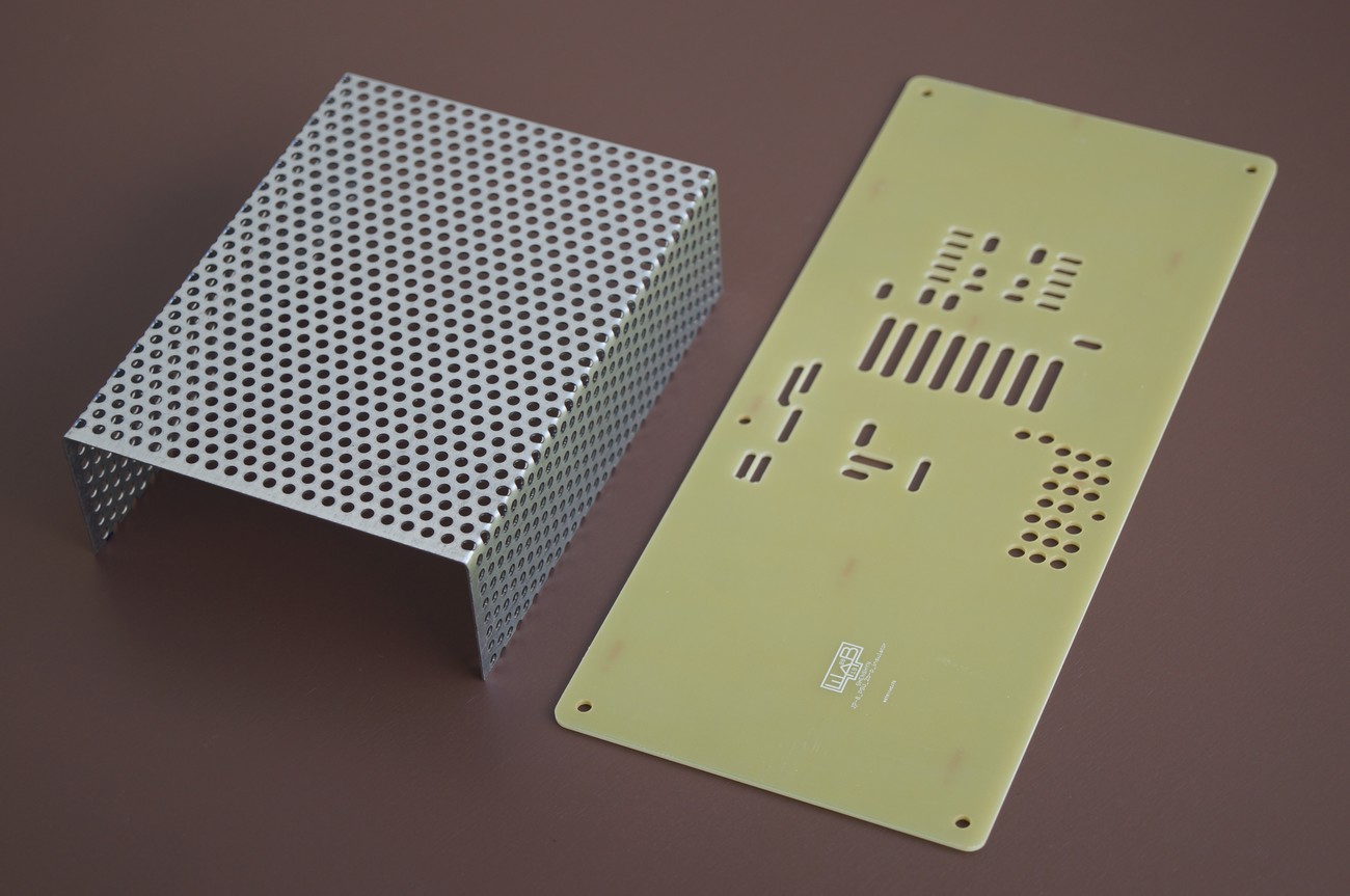
- Top metal protection cover and bottom insulator plate that covers all components under high voltage
- Compact construction
- Easy to install
- For sale complete PSU module incl. insulator board and protection metal cover + all necessary parts to install the PSU
- Price: 390€ net

Auxiliary mounting parts
Not depicted, but will be supplied:
VAC IN 85..265V 50..60Hz label
15 cm cable to connect PSU and line switch
total 12x DIN934 M3 nuts
Technical information
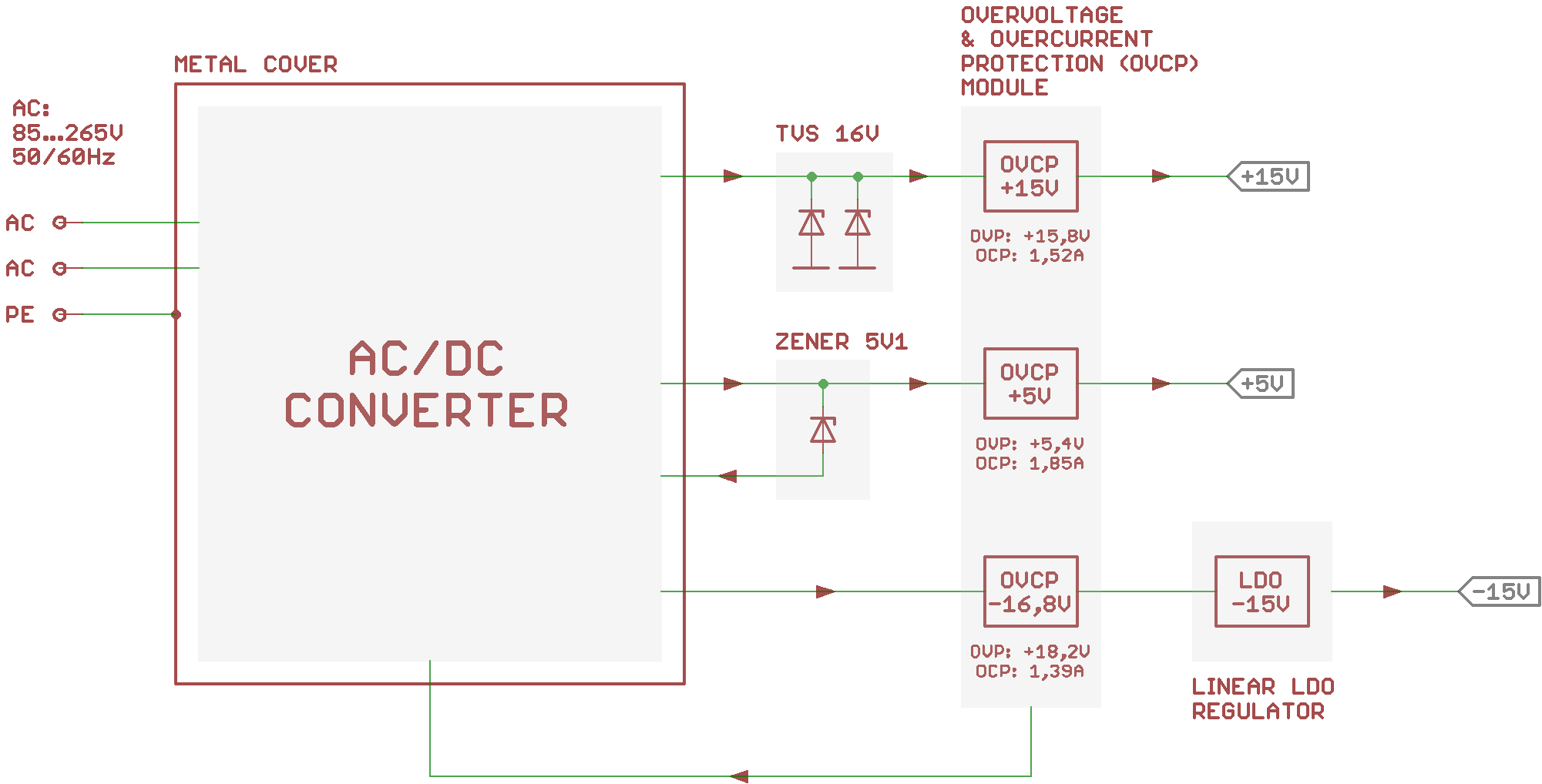
Below block diagram of PSU is depicted. It consists of AC/DC converter, Zener Diode (ZD) / Transient Voltage Suppressors (TVS), Overvoltage and Overcurrent Protection (OVCP) Module and LDO regulator
AC/DC converter
The converter has an universal 85…265VAC 50/60Hz input. It has internal over-load/temperature protection. If over-load/temperature event occurs, the AC/DC converter latches off (to be precise, it stops to switch and produce output voltages; the converter primary high voltage stage is still powered with a line voltage). Disconnecting of the PSU from the line voltage will reset the converter and if no fault condition is present it will start to work normally.
AC/DC converter uses multiple output flyback topology and the +5V rail should be always loaded with at least 500mA. To avoid useless losses in the converter, there is no internal pre-load resistor inside (as it is usual for normal multi output PSUs on the market), so be sure +5V rail is connected to the synth circuitry. At the same time +-15V rails should be also connected to the synth circuitry.
Zener Diode (ZD) / Transient Voltage Suppressors (TVS)
16V TVS diodes clamp the overvoltage on +15V rail. If PSU is working properly and loaded properly, the +15 rail has 14,9V…15,1V. If +5V rail is overloaded (for example when PSU is shorted or some defective electronic component draws more current), the voltage on +15V will also increase (up to 2V) (this is normal behavior of the PSU). 16V will clamp the overvoltage. But, before TVS diodes will start heavily clamp the voltage, the OVCP module (see below) will latch off the AC/DC converter (at around +15,8V).
Zener diode 5V1 is connected to the +5V rail. If the voltage on this rail exceeds +5,5…6V, the converter will latch off. But before this happens OVCP module reacts at +5,4V.
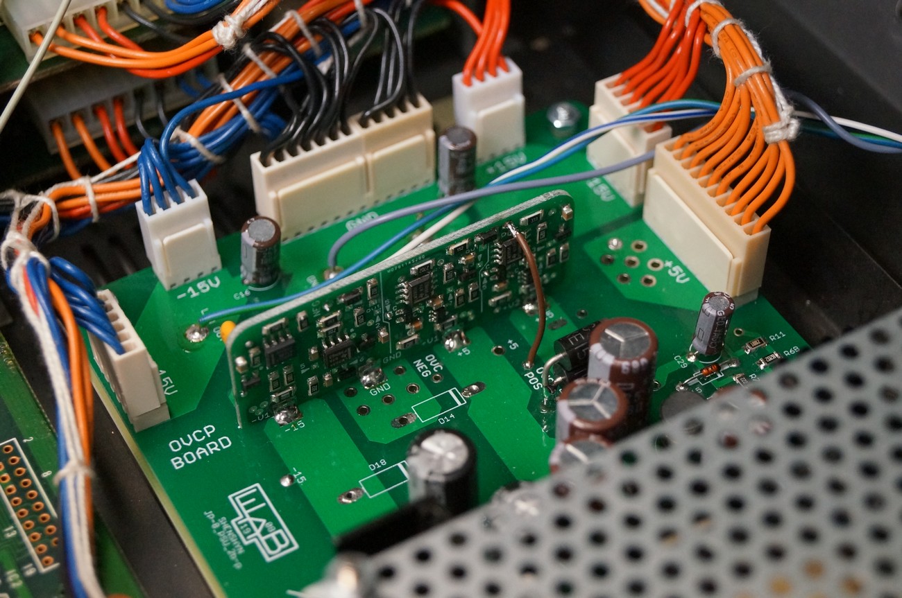
Overvoltage and Overcurrent Protection (OVCP) Module
Overvoltage and Overcurrent Protection Module has precise voltage and current sensors for every rail. OVCP module is connected to the AC/DC converter controller IC. If any of following events occurs, the AC/DC converter will latch off (as described above in the „AC/DC converter“ part):
- Voltage on +5V rail raises to +5,4V
- Voltage on +15V rail raises to +15,8V
- Voltage on -15V rail (before LDO regulator) raises to -18,2V.
- Current on +5V rail raises to 1,85A (normal Jupiter 8 +5V rail consumption is 1,5A)
- Current on +15V rail raises to 1,52A (normal Jupiter 8 +15V rail consumption is 1,1A)
- Current on -15V rail raises to 1,39A (normal Jupiter 8 -15V rail consumption is 1A)
Current and voltage sensors have tolerances +-2{eb681a58ecc476759952a50a8a7c167279151df38e58f2598760f2d2e5f4f286}
Linear LDO regulator
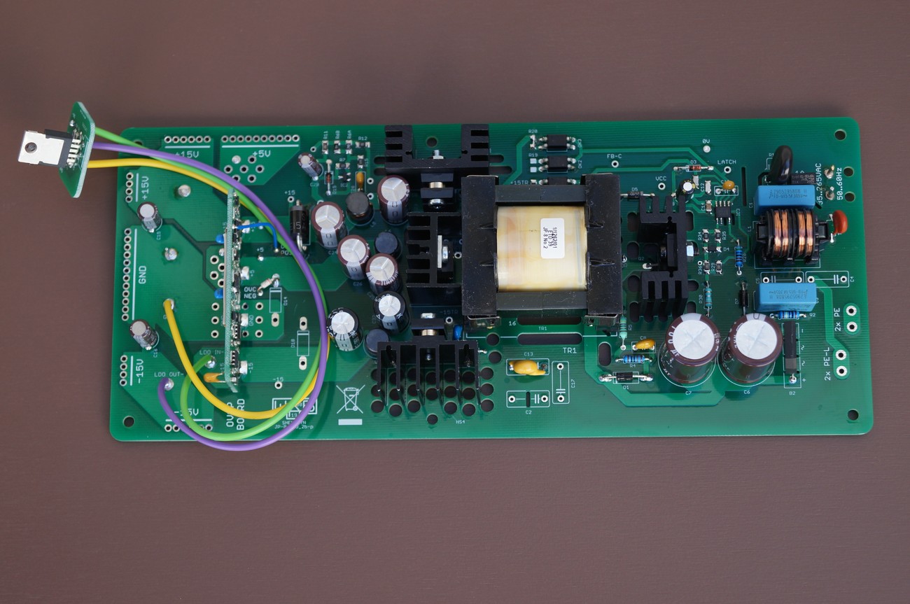
Regulates the AC/DC output approx. -17V to precise -15,000V, as required in service manual. The -15V LDO regulator is placed on separate PCB and is mounted on the original JP-8 heatsink (see below)
A small SMD potentiometer is located on the LDO regulator board and it is possible to adjust exact -15,000V
Why a LDO regulator is not used on +15V rail?
- When building a multi output flyback converter, it is hard to obtain precise voltages on every rail at nominal load. In our case, it was possible to get precise +5V an +15V, but not -15. So higher voltage is produced and then regulated down to -15V
- Service manual requires precise voltage at -15V rail, that is achievable with a linear regulator. In contrary, +15V rail have wider voltage tolerances and a LDO regulator is not necessary
- Not using a +15V regulator avoids around 3W losses in the LDO, output rectifiers and transformer
- JP-8 works great without the LDO on +15V: there is no pitch deviation or extra audible noise
As conclusion, this PSU has superior protection against fault conditions:
Triple OVP protection:
- precise voltage sensors as a part of OVCP module
- clamping with 5V6 and 16V TVS diodes
- controller IC OVP circuit
Double overcurrent protection:
- coarse over-current and short circuit protection as a part of controller IC circuit
- precise current sensors as a part of OVCP module
Installation instructions
PLEASE NOTE! We sell a fully working and tested PSU with few additional parts to mount the PSU into the Jupiter 8. Following installation is an example. We are not responsible for health injuries and material damages that can cause bad installation of this PSU. Only a qualified tech should make this PSU swap. You are doing the PSU swap on your own risk.

Unplug the power cord!
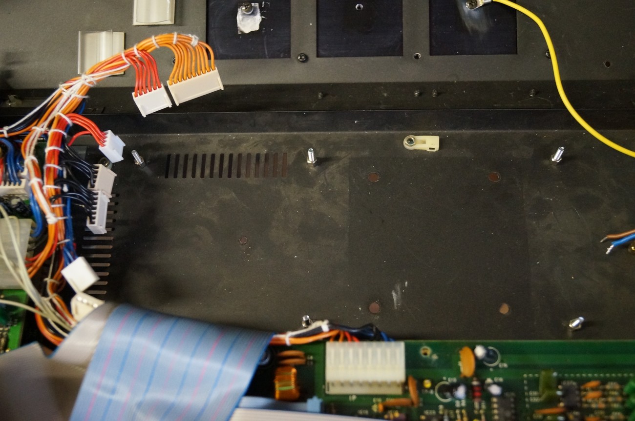
Remove old PSU parts as depicted
Cut the wires that are soldered to distribution eyelets +5 (orange), +15 (red), -15V blue and GND (black) on the left side of the PSU board. Cut as close as possible to the eyelets so that you don’t waste the length of the wires.
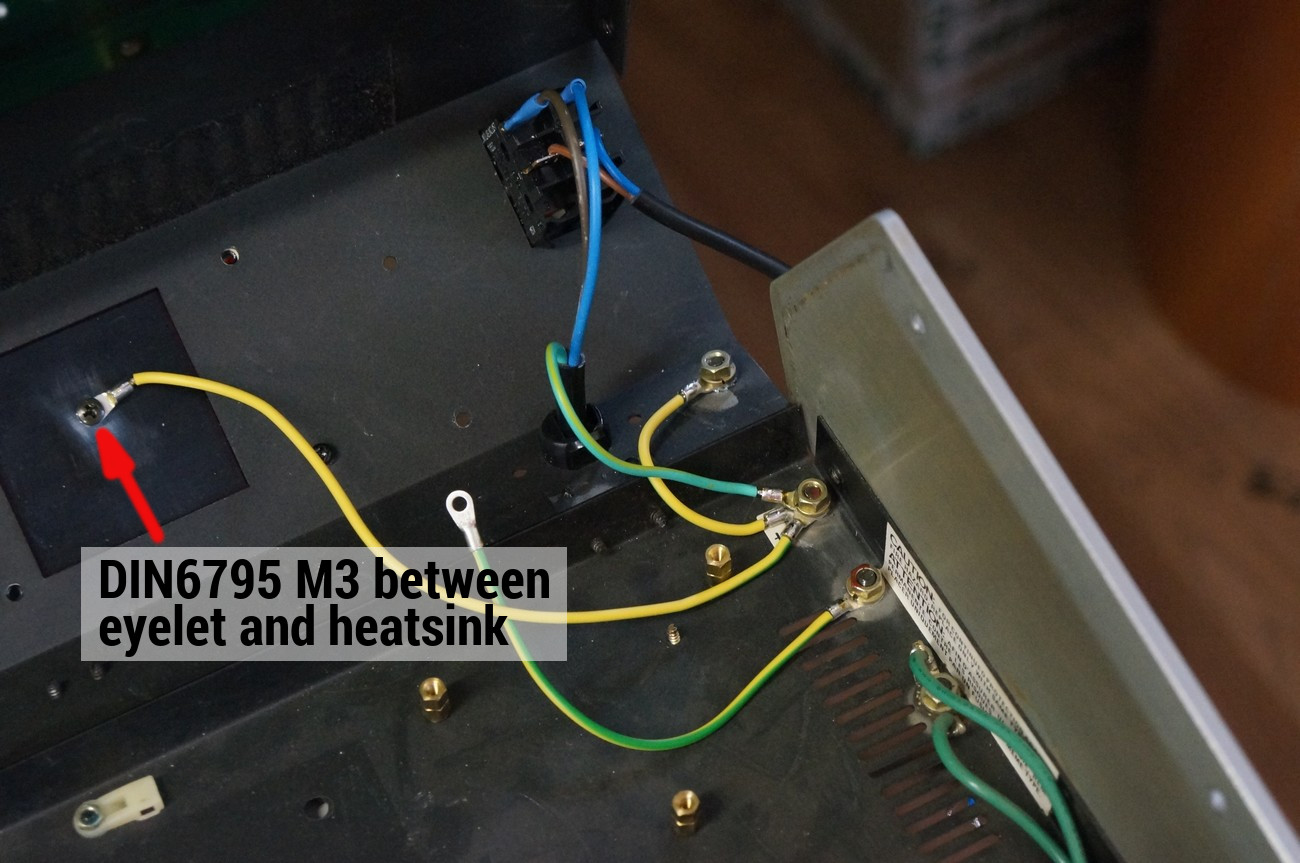
Connect all 3 earth cables as depicted. The connection should be STRONG. Use original screws and washers/nuts.
Solder N and L wires of the line cable directly to the line switch.
Solder another N and L wires (length approx 15cm) to the other two pins of the switch. These two wires will be later connected to the PSU
Remove 7x old spacers from the metal chassis and mount 6x new 5mm spacers as depicted
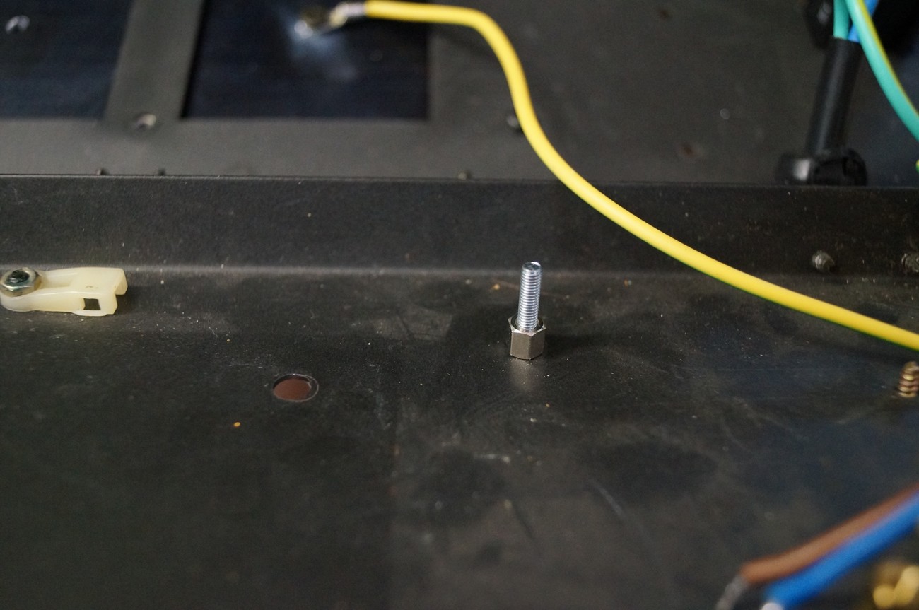
Like this
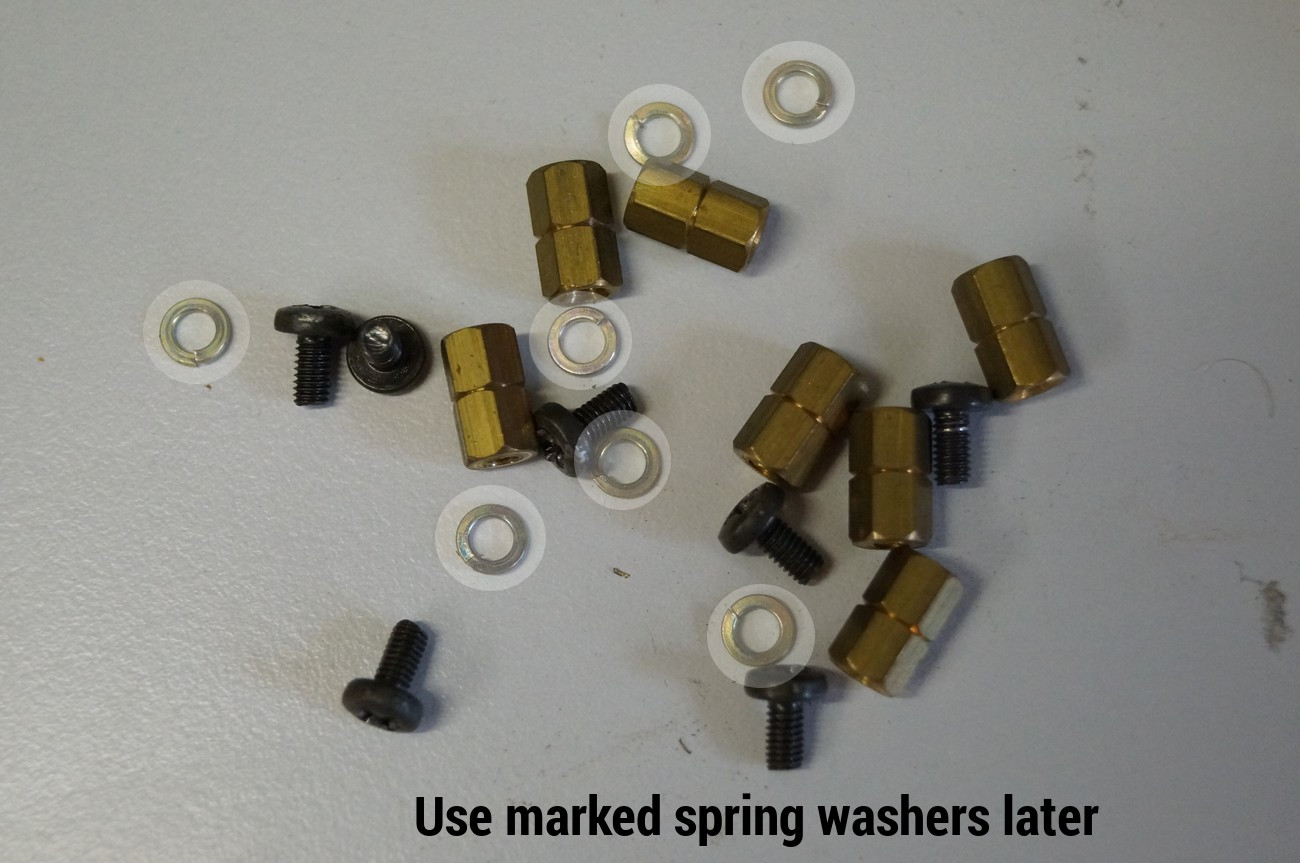
The old spring washers will be used later

Now place the insulator PCB on 5mm spacers, as depicted
Fasten it with 6x DIN934 M3 nuts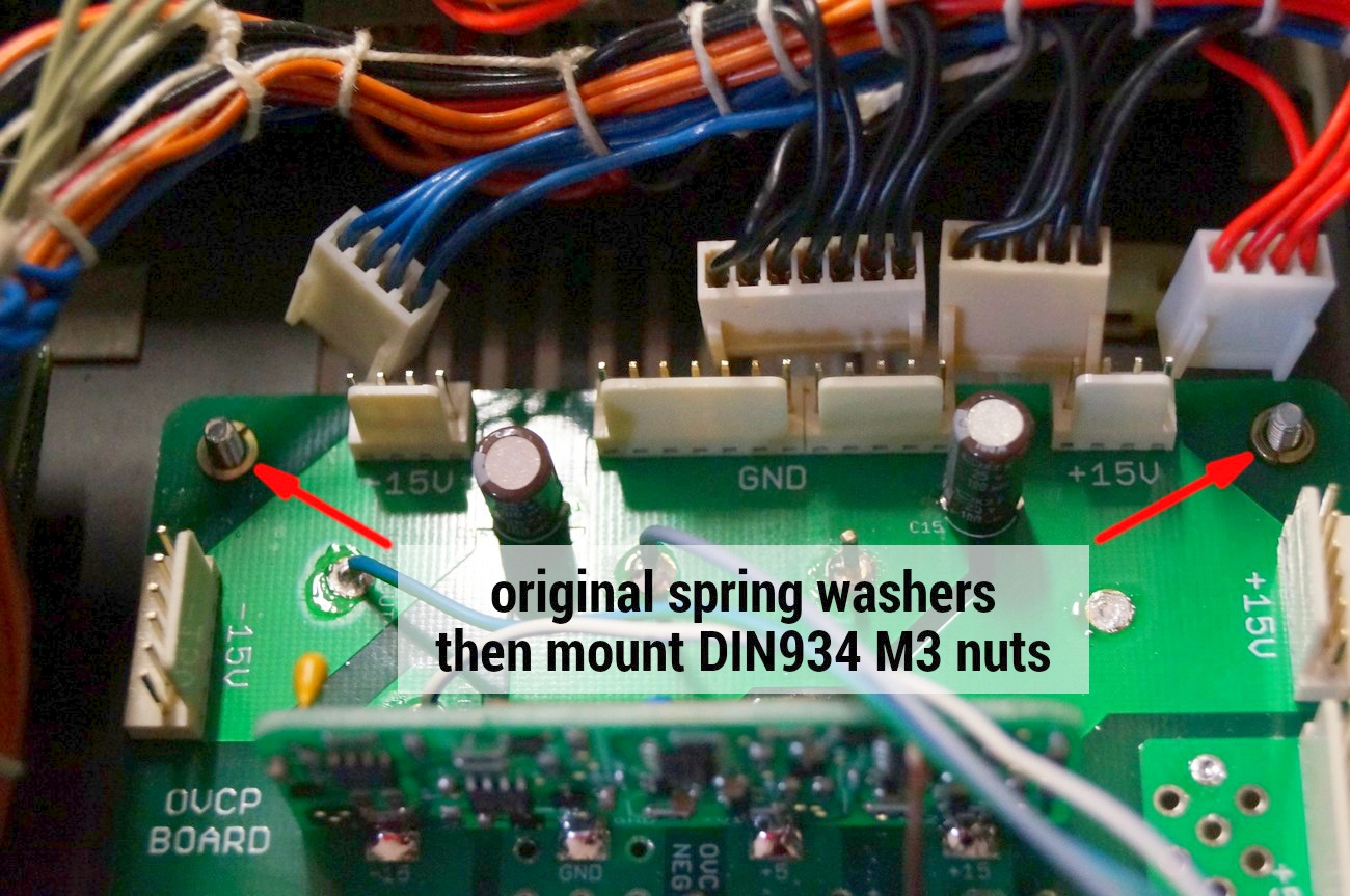
Now put the converter PCB on the nuts.
Before this step, you should remove the insulation from wires. If desirable, mount there 2,54 Molex connectors instead of soldering
Place original spring washer and then fix with M3 DIN934 nuts
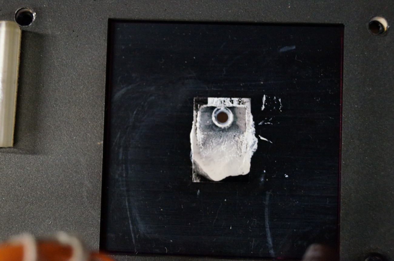
Now installing of the mica TO-220 insulator
Unpack it carefully from the paper cover
Place some heatsink paste on the heatsink (the most left cutout in the metal case)
Put there the mica insalator so that both holes are CENTERED! This is very important to avoid a damaging of the insulator when installing the LDO
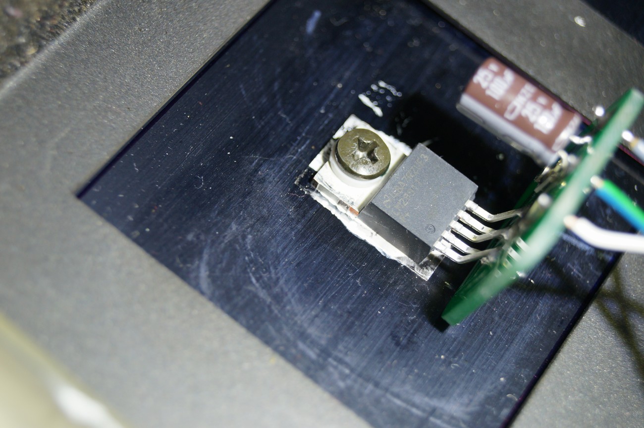
Use original screw and put the TO-220 insulator ring on it. Then put it into the regulator’s hole and screw carefully to the heatsink. Again, be very soft and pay attention that the mica insulator doesn’t move to the side. Otherwise it will be damaged and the metal tab of LDO will be electrically connected to the heatsink what is forbidden.
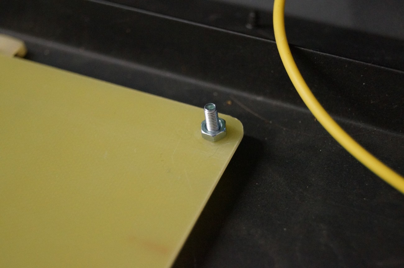
Now, install the metal cover. At first screw 4x 40 mm spacers (these consist of two parts, for example 25 + 15 or 20 + 20 mm)
Put the metal case on mounted 40mm spacers
Put the original spring washer on the screw thread and then fasten with M3 nut…
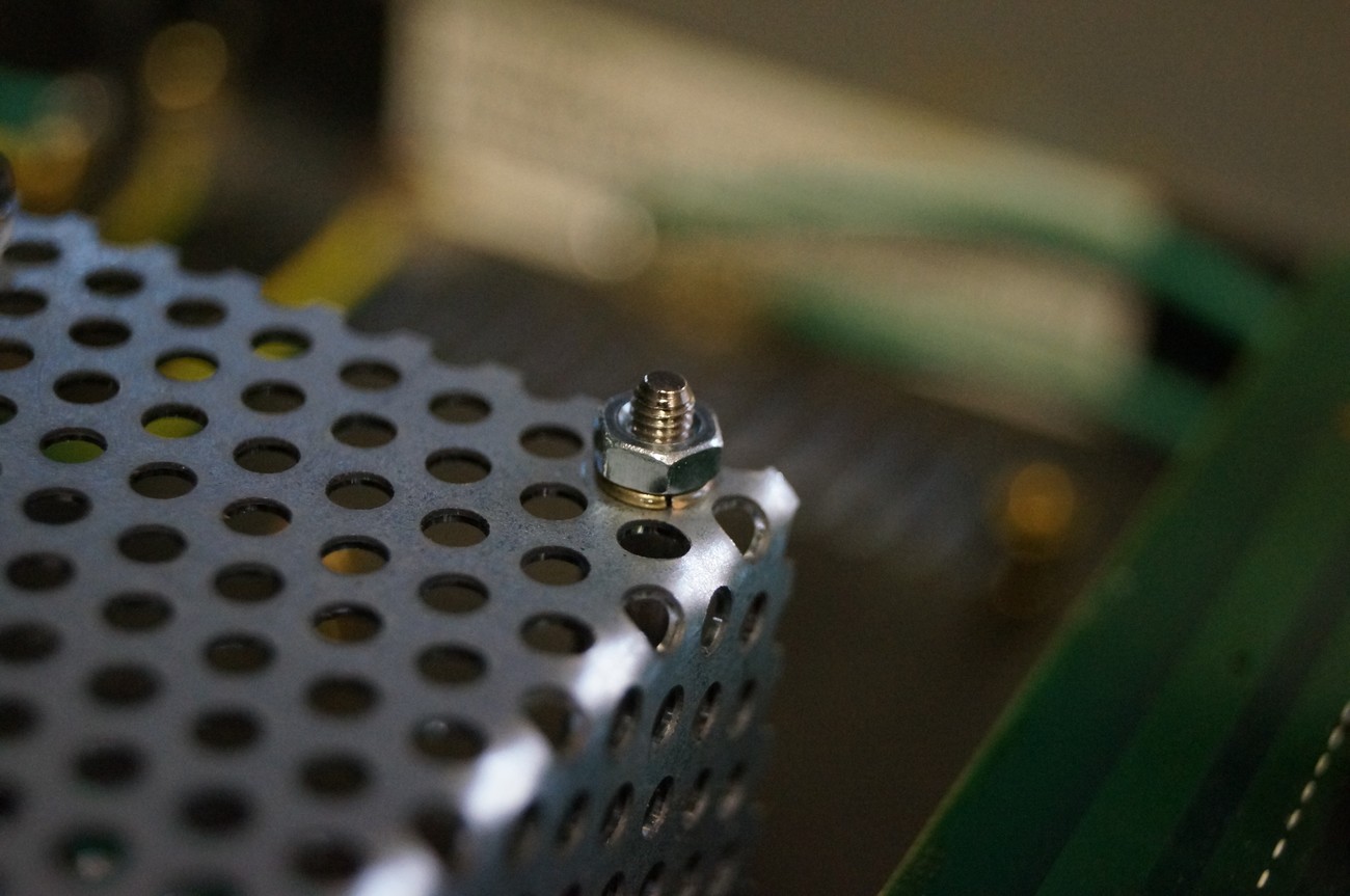
… like this

Now, connect middle earth cable to the metal cover. Use original spring washer and DIN985 M3 nut
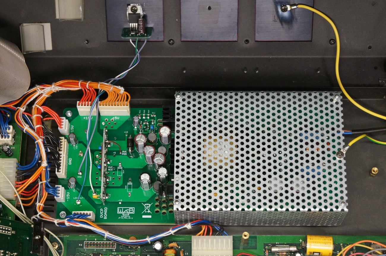
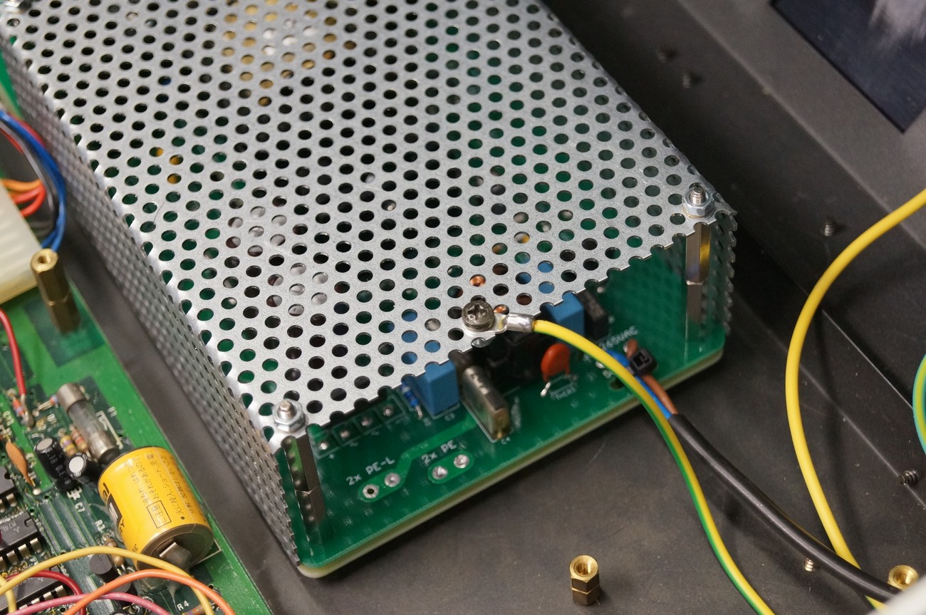
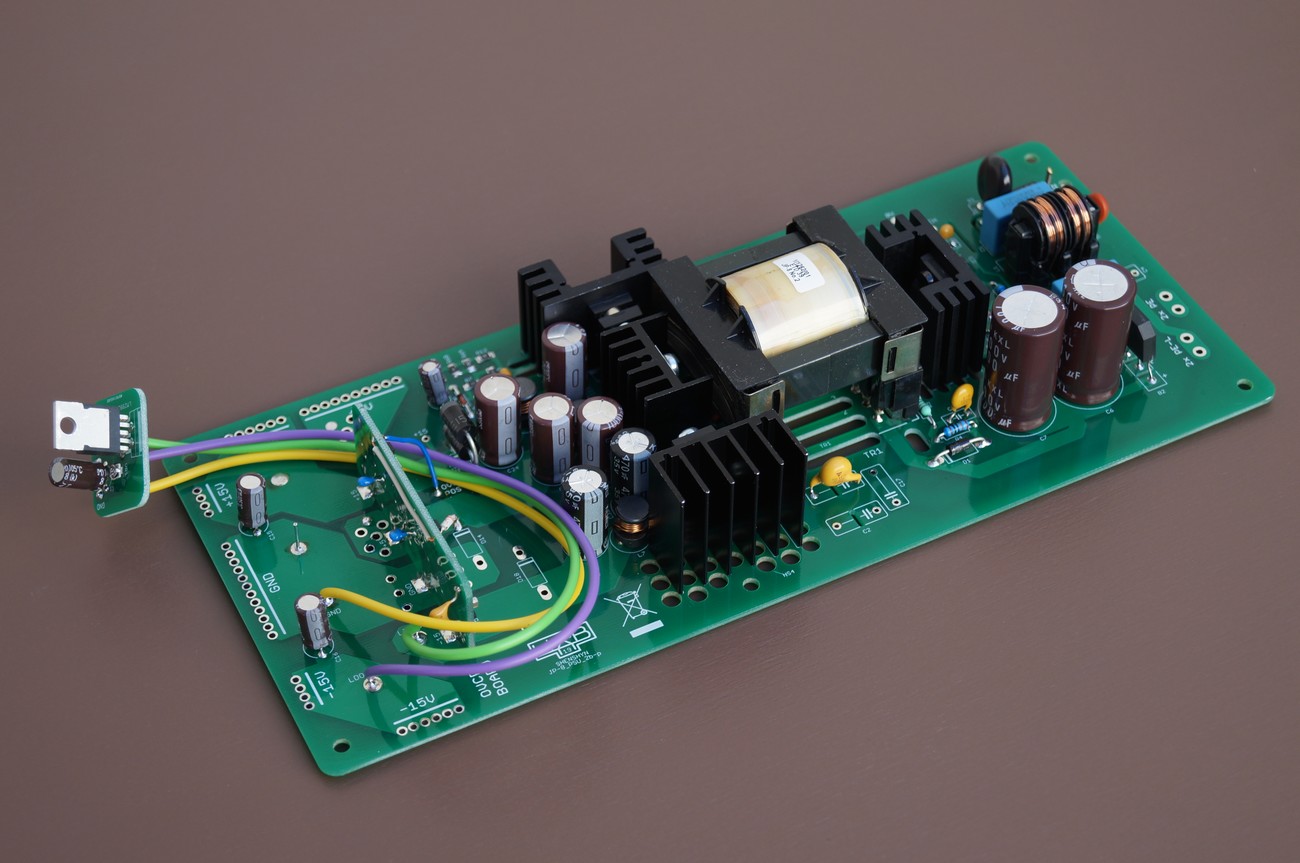
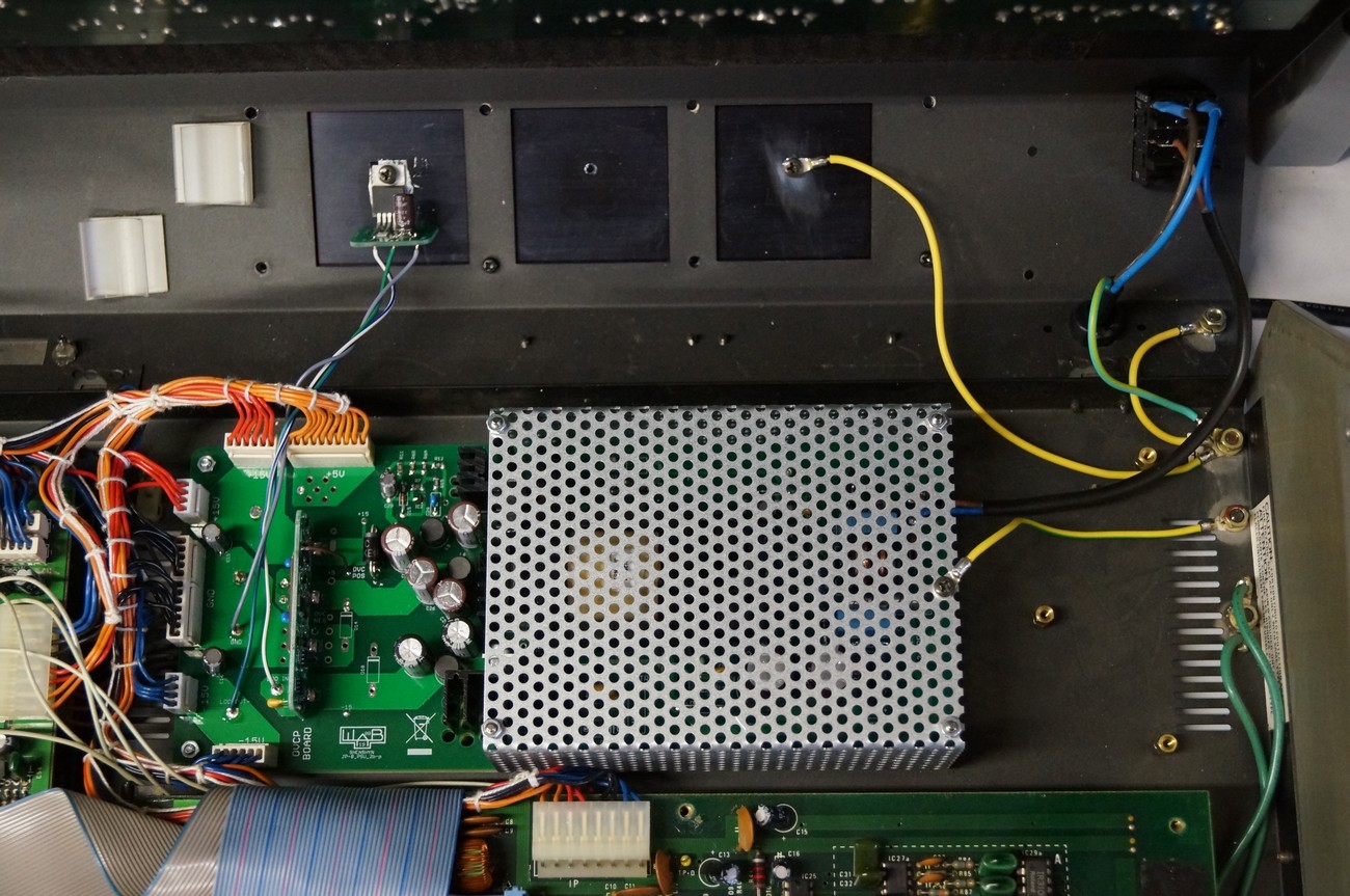
Now, the PSU looks like this. PE wire is NOT connected to the converter board
Before connecting of +5, +15, -15 rails to synth boards, check the PSU voltages. Connect 10 ohm resistor (power rating at least 5W) or 5 ohm resistor (power rating at least 10W) between GND and +5V rails. Check all voltages on the PSU (with scope or DVM). If everything is OK, solder all wires to the PSU board (or just plug the connectors if you installed them before)
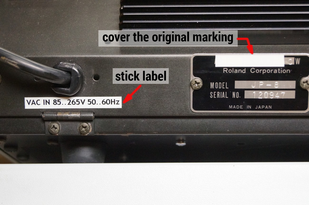
Add VAC IN 85..265V 50..60Hz label and cover the original voltage marking
READY!
Some safety recommendations when working with the PSU
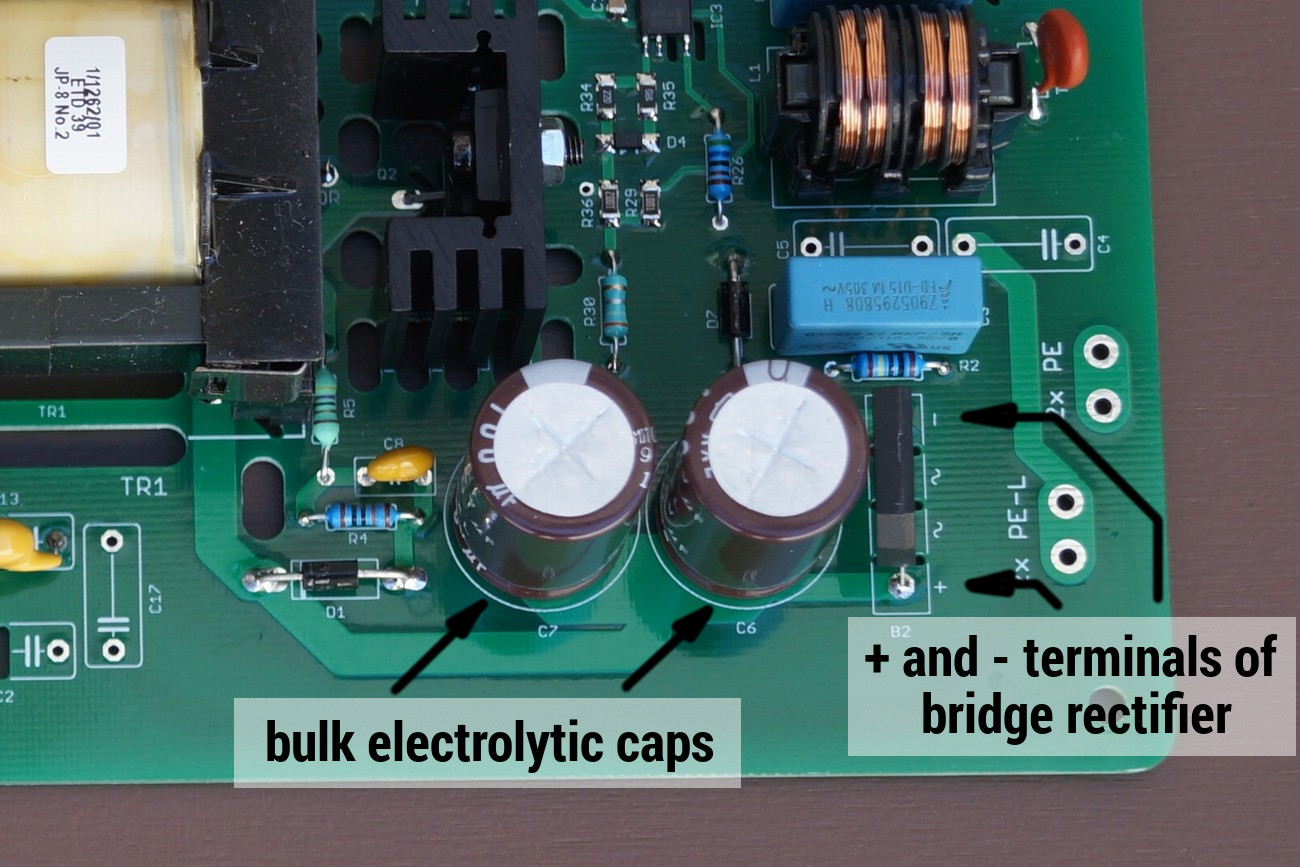
- Be careful, the big bulk electrolytic cap is still charged with high voltage (for 115VAC it is 165V and for 230VAC it is 330V) after the PSU was turned or latched off
- When de-installing the PSU, short + and – terminals of the bridge rectifier with a 470 ohm / 5W resistor for 1 second. At this time, PSU should be disconnected from the line voltage