Linndrum PSU replacement
About Linndrum PSU (power supply) replacement
This new PSU was made to replace the old Linndrum PSU. Unfortunately the original PSU has a lot of disadvantages and design issues that decrease the reliability of Linndrum machine:
- Heat! The biggest problem in these units. Rectifier diode 1N5400 is not suitable for this application because it overheats. Overheat destroys the PCB and heats the electrolytic cap nearby. Linear regulators don’t have sufficiently big heat sink, so they get too hot. Again, it heats unnecessary electrolytic caps nearby.
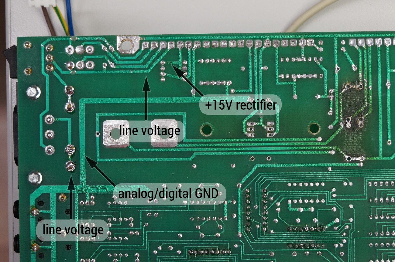
- PSU is not separated. Part of PSU is on DRM board. That is a bad solution. On some places there is a line voltage trace next to +15V supply trace (less than 1mm distance). This is dangerous. If both traces get connected together, it will destroy all (expensive) chips in the machine (AD6070, CEM3320 ant others).
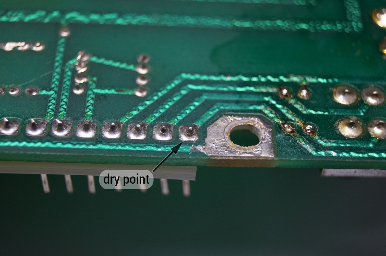
- Dry points between connectors and PCB.
- Relatively high weight (1,7kg).
- Too low efficiency (around 35{eb681a58ecc476759952a50a8a7c167279151df38e58f2598760f2d2e5f4f286}).
- No line filter. The noise can easily get into the device.

To remove these issues would require the change of original transformer, new +5V DC-DC converter, diodes and linear regulators. Even after that the PSU would be not as good as it can be. So only new and tailored-made PSU can give the best result. And, here it is!
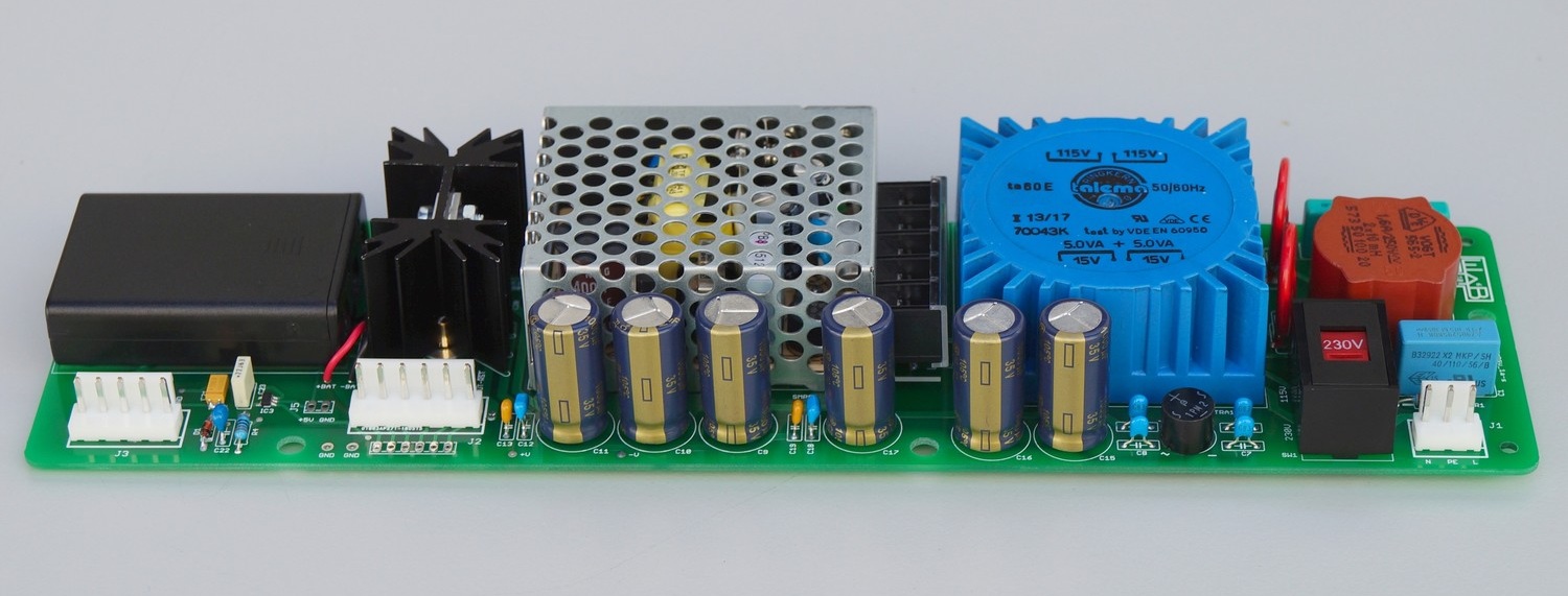


New PSU that solves all listed problems:
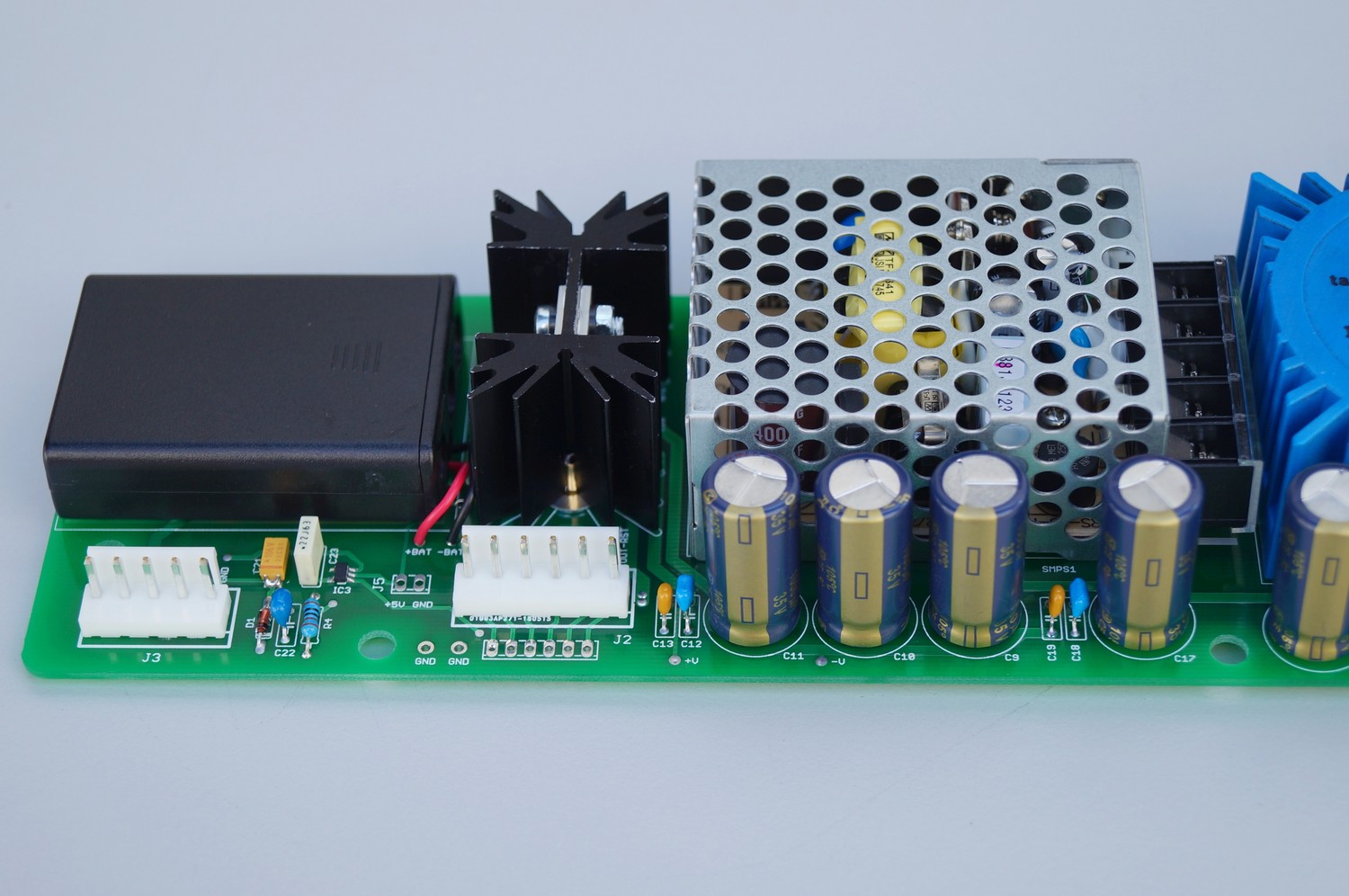
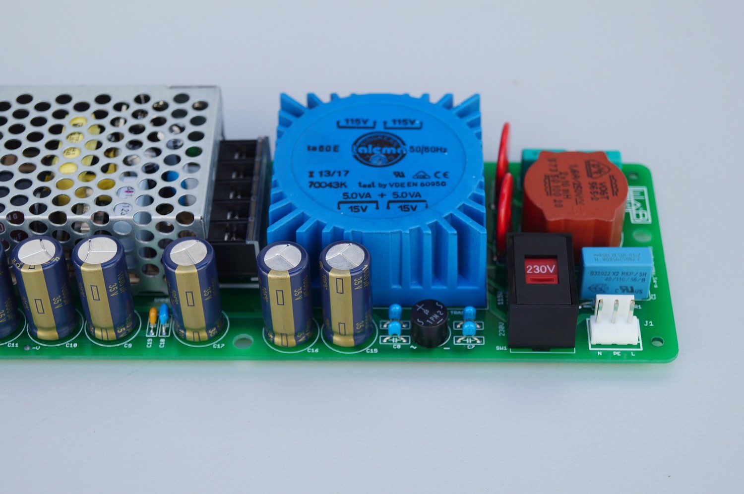
- +5V uses a high quality Meanwell SMPS with a typical efficiency 77{eb681a58ecc476759952a50a8a7c167279151df38e58f2598760f2d2e5f4f286}. +-15V supply rails produce LDOs. LDOs have low dropout voltage, that’s why they are more efficient than normal linear regulators. The unregulated voltages for LDOs are made by a high efficient (82{eb681a58ecc476759952a50a8a7c167279151df38e58f2598760f2d2e5f4f286}) TALEMA toroidal transformer. Filter caps are high quality from Panasonic. The transformer has a robust EMI filter that reduces line noise and noise from the switch.
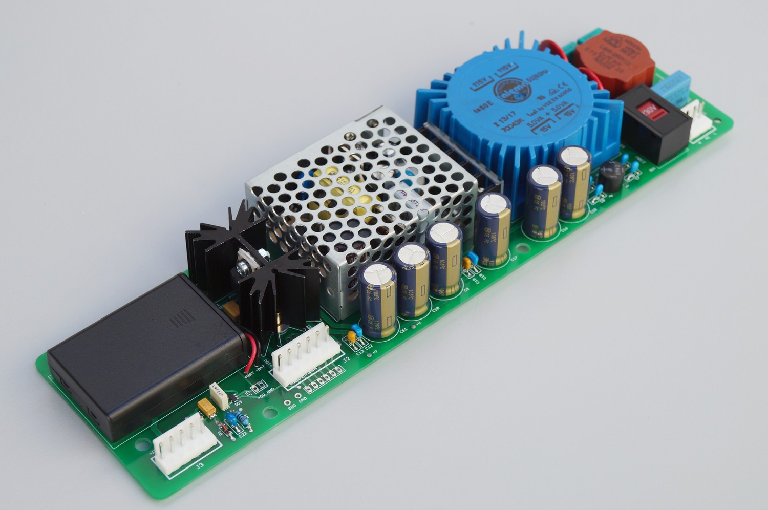
- The PSU is very compact and is completely build on one separate PCB. It fits perfectly into the drum machine. The special insulator PCB isolates metal chassis from line voltages that are on bottom side of PSU PCB. After removing of all old PSU related parts on a DRM PCB, there are no more critical places with too close line/low voltage traces.
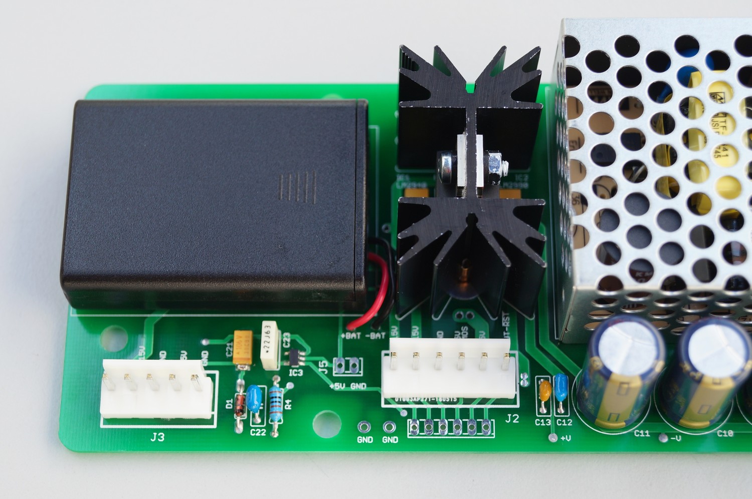
- New JST connectors are used. This makes connector resistance very low.
- The whole PSU module weights only 0,6kg. That is almost 3 times less than original PSU.
- The total efficiency is around 65{eb681a58ecc476759952a50a8a7c167279151df38e58f2598760f2d2e5f4f286}.
New PSU contains three NiMH cells that supplies preset-SRAM with voltage when the device is off. It also produces correct reset signal for RAM circuitry.
To install the new PSU it is necessary to remove the whole old PSU.
PLEASE NOTE! We sell a fully working and tested PSU with few additional parts to mount the PSU into the drum machine. The following installation is an example. We are not responsible for health injuries and material damages that can cause bad installation of this PSU. Only a qualified tech should make this PSU swap. You are doing the PSU swap on your own risk.
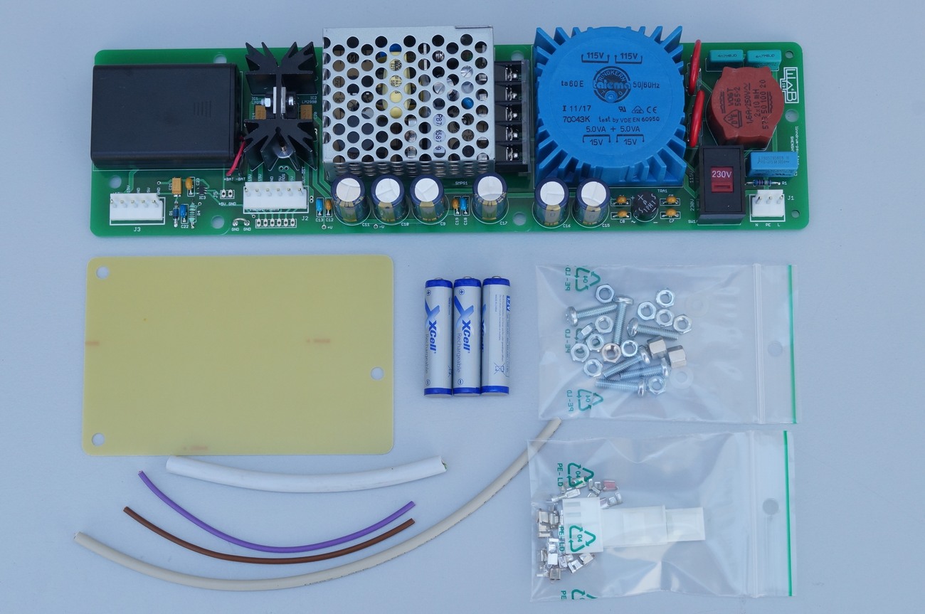
Replacement PSU Kit
- 1x completed and tested PSU
- 1x insulator plate
- 3x NiMH cells
- 6x M4, 16mm screws DIN 7985
- 12x short M4 nut DIN 934
- 3x long M4 nut 6mm
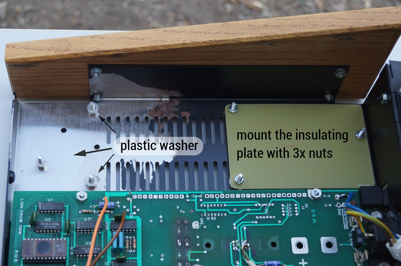
- 3x plastic washer M4
- 3x connector housings (3, 5 and 6 pin)
- 15x connector crimp contacts
- 1x cable set to wire up the new PSU
Installation instructions
These instructions describe a complete installing of the PSU replacement into an old revision of Linndrum. New revision has slightly different PCB. Below, on two places, it is also mentioned how to proceed when installing into a new rev. Linndrum. That means these installation instructions are suitable for both Linndrum revisions
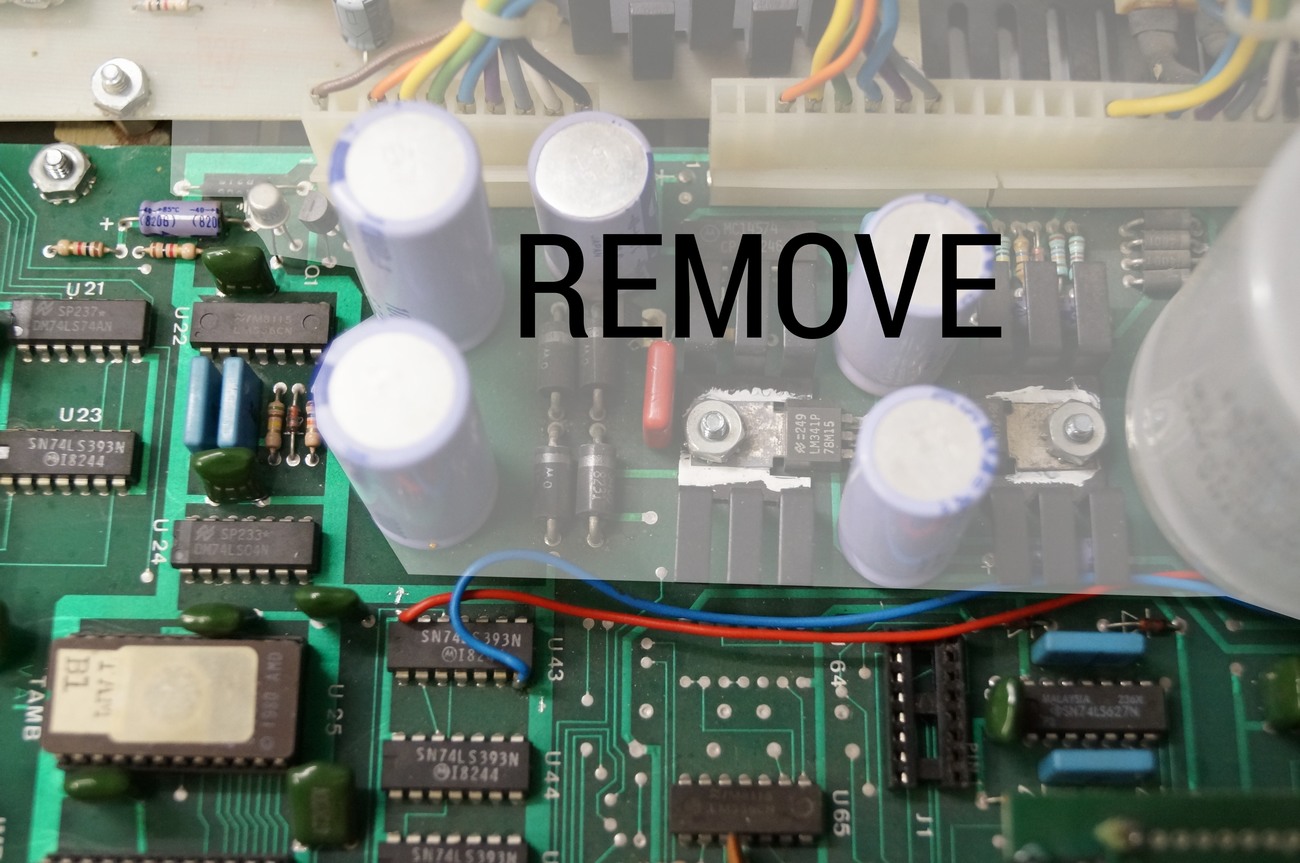
Remove all PSU related parts: white marked parts on DRM board (old revision) and 5VSR board.
DRM new revision: remove also marked axial electrolytic cap and 1k resistor (code brown-black-red)
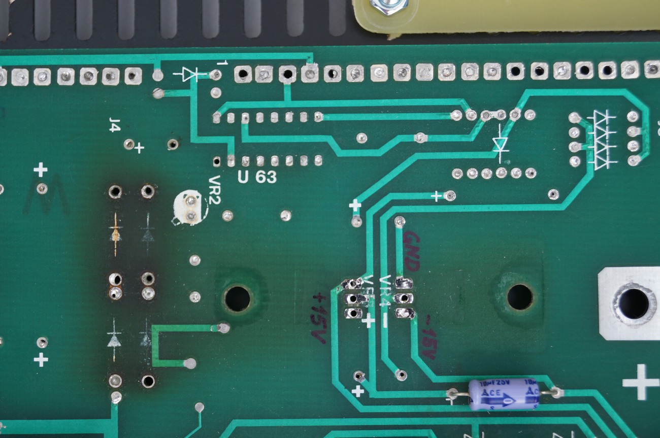
Your board should look like the board in this picture.
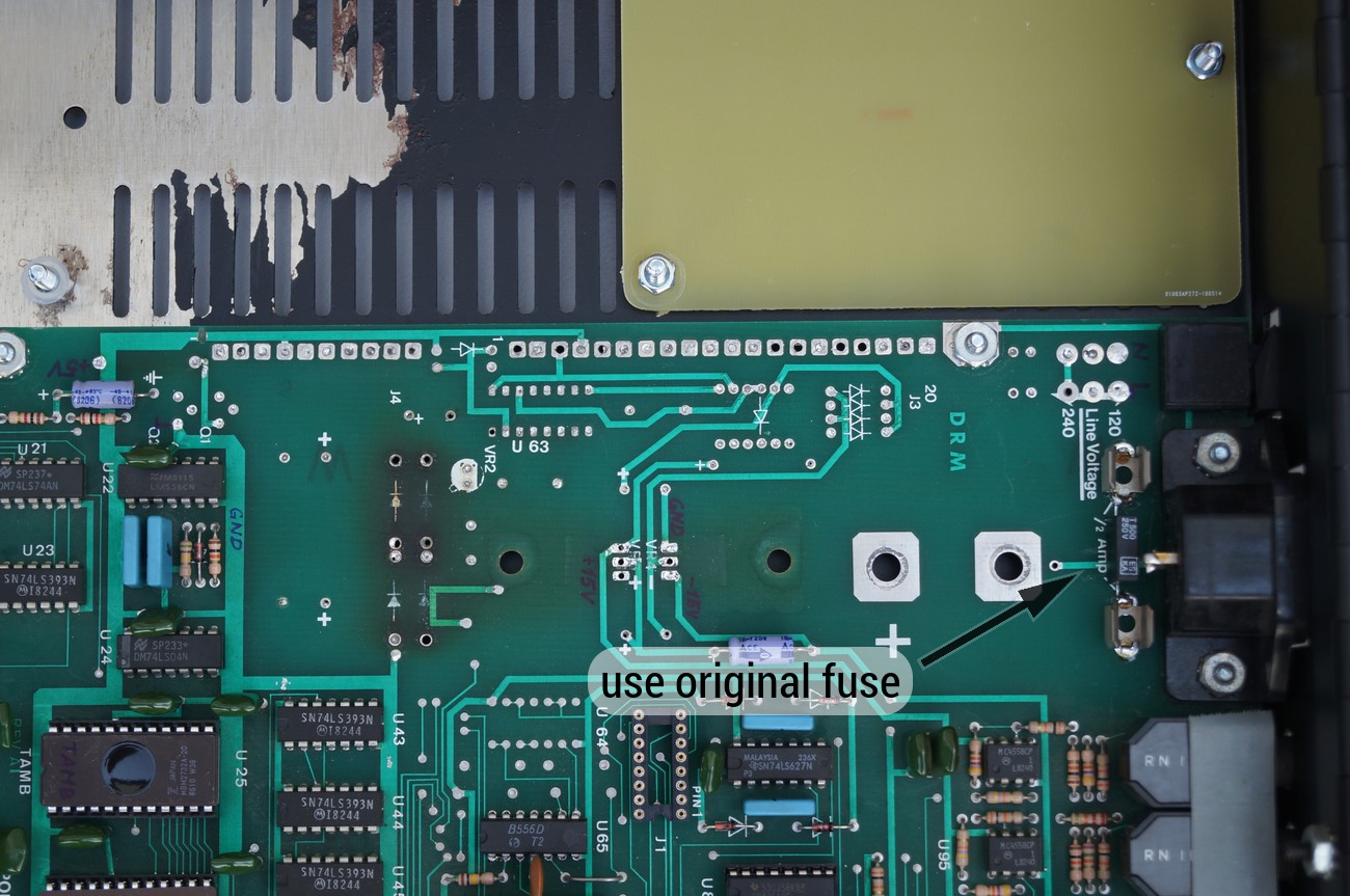
Use original fuse holder and fuse.
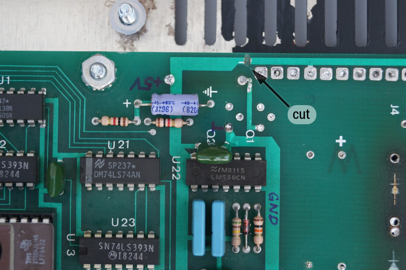
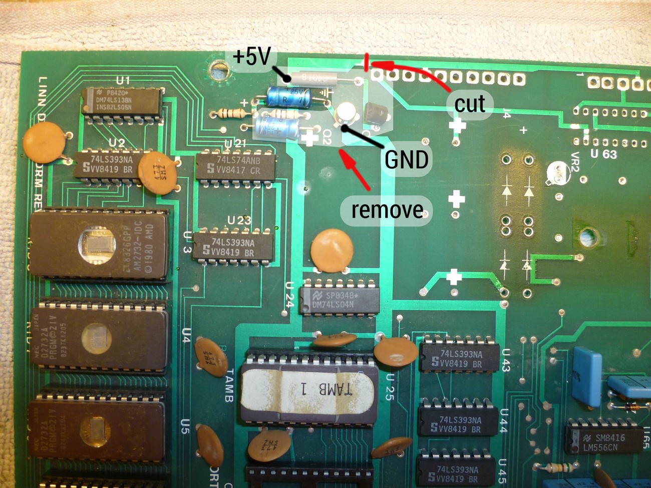
Mark traces as above. Cut the trace as on the photo.
Mark traces as above.

Now bottom side.
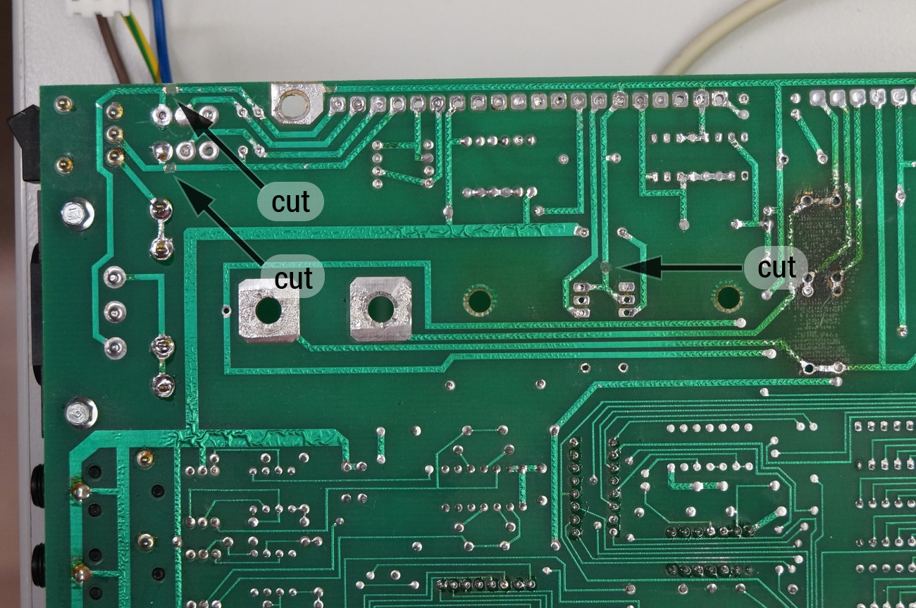
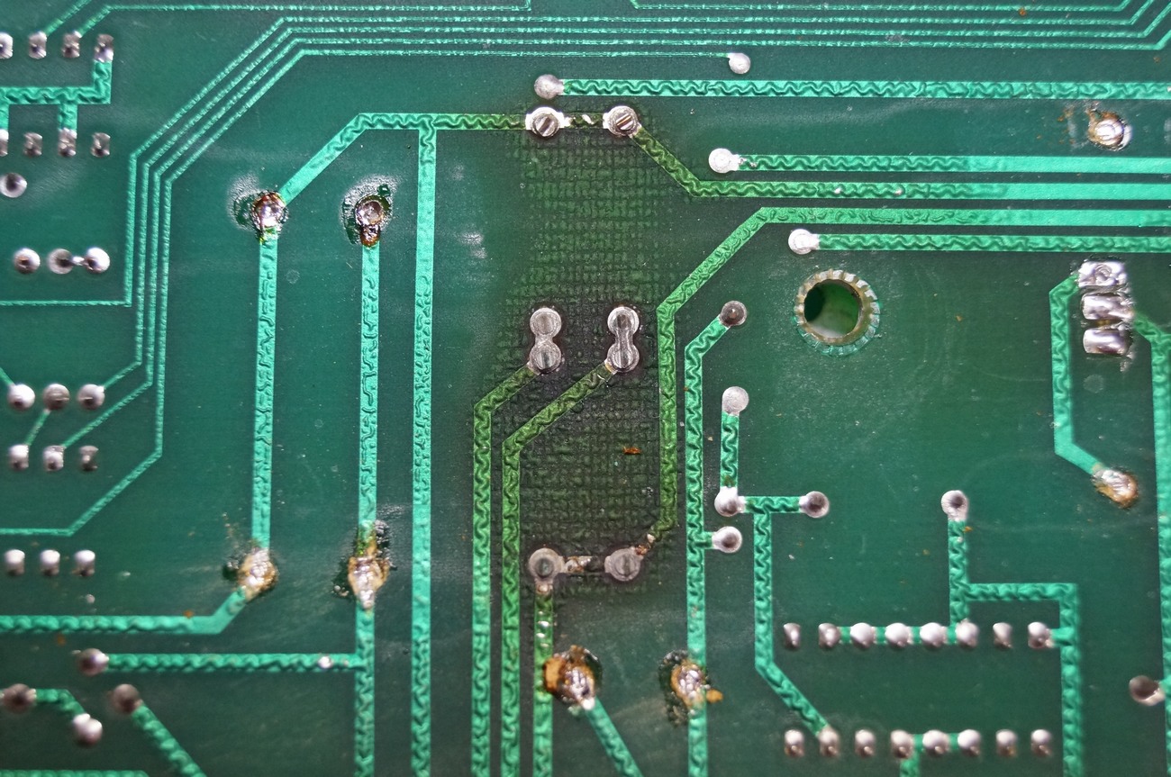
Cut 3x traces as on the photo.
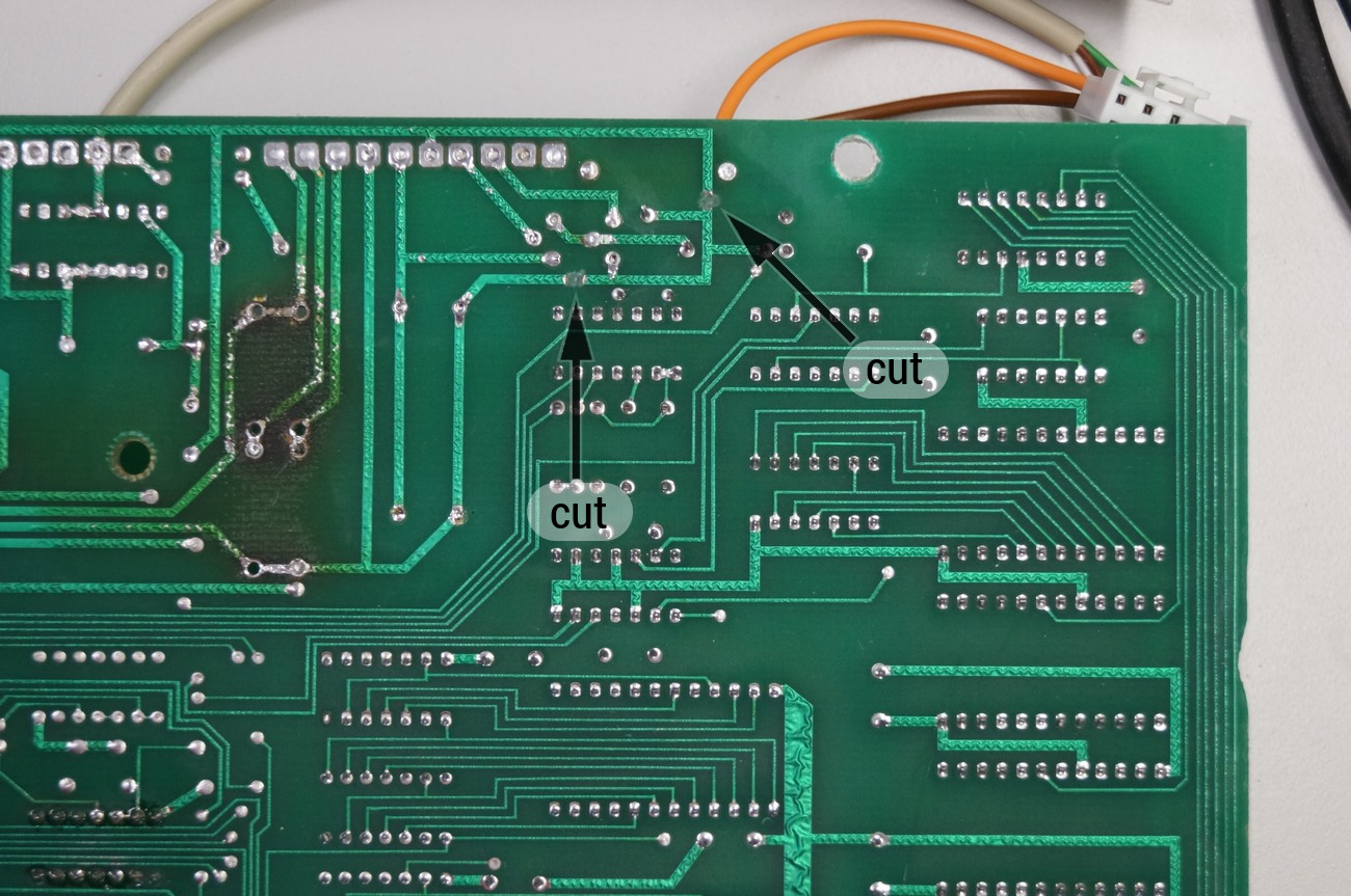
Cut 2x traces as on the photo (DRM PCB old revision).
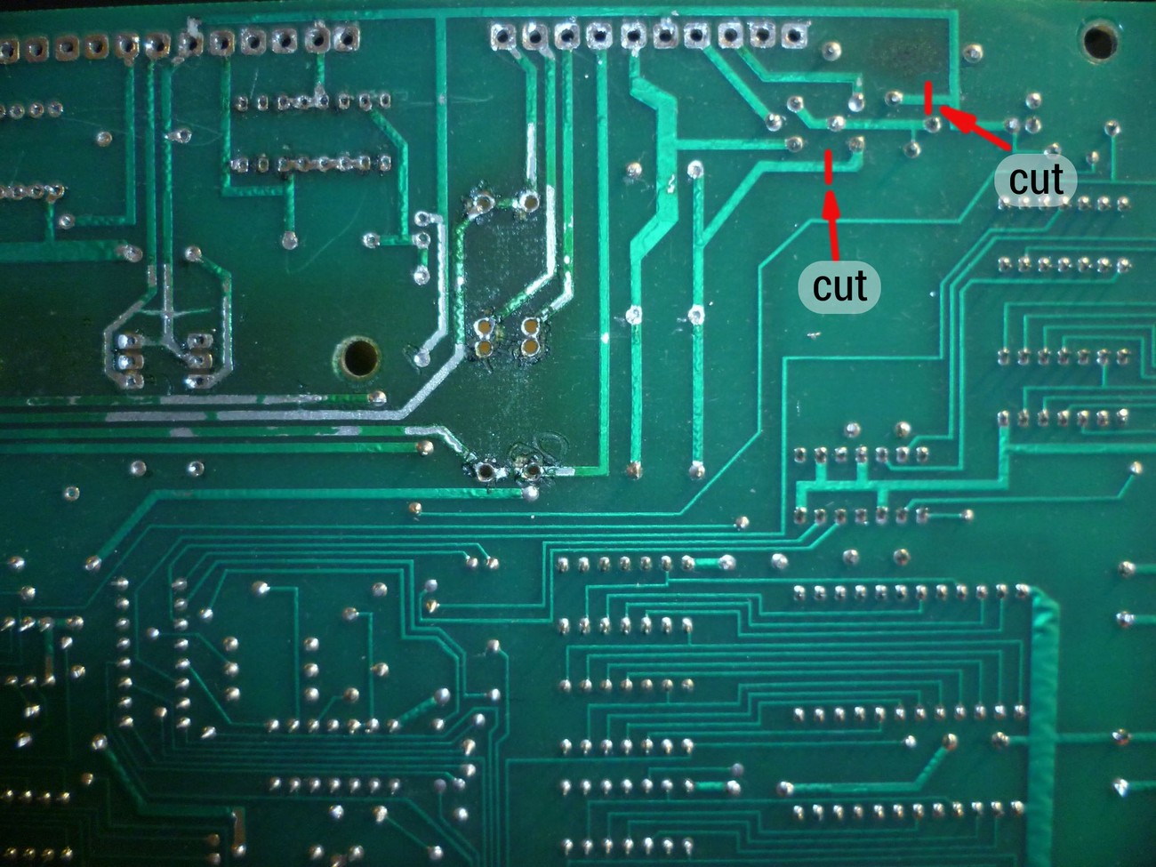
Cut 2x traces as on the photo (DRM PCB new revision).
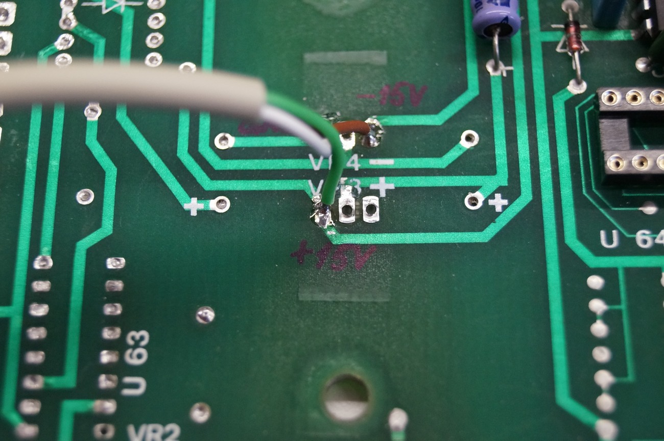
Isolate cable and wires and solder to already marked pads.


Line wires. Be sure, power cord is unplugged!
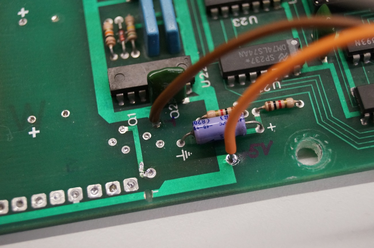
+5V wiring.

PSU connector on the CPU board – pin description
d
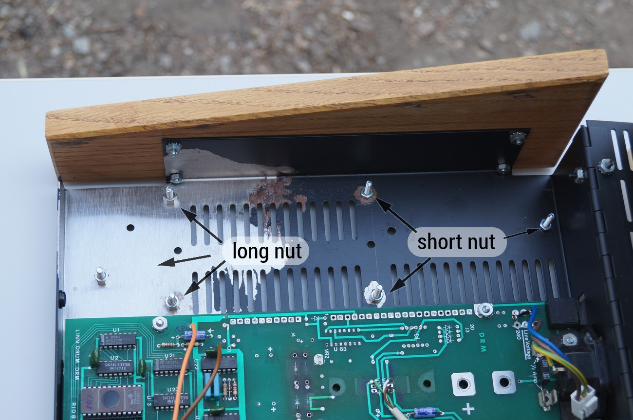
Now mount the PSU PCB:
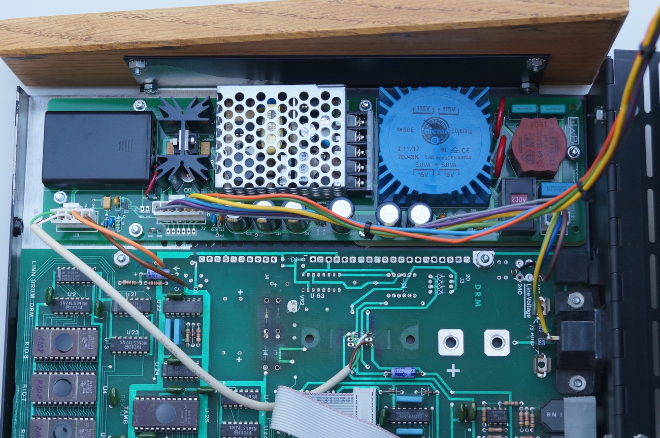
When PSU is mounted, double check everything and plug J1 connector on the PSU board (line voltage).
Turn on the mains switch and check all voltages on J2/J3. All voltages should be present. Turn off the device.
Be sure wiring between PSU and DRM/CPU board is correct.
Plug J3 and J2 to the PSU.
READY!
Pricelist (in EUR) & ORDERING
Please, place an order via E-mail! Normally we response within 12 hours.
![]()