Korg Polysix PSU replacement
About Korg Polysix PSU (power supply) replacement
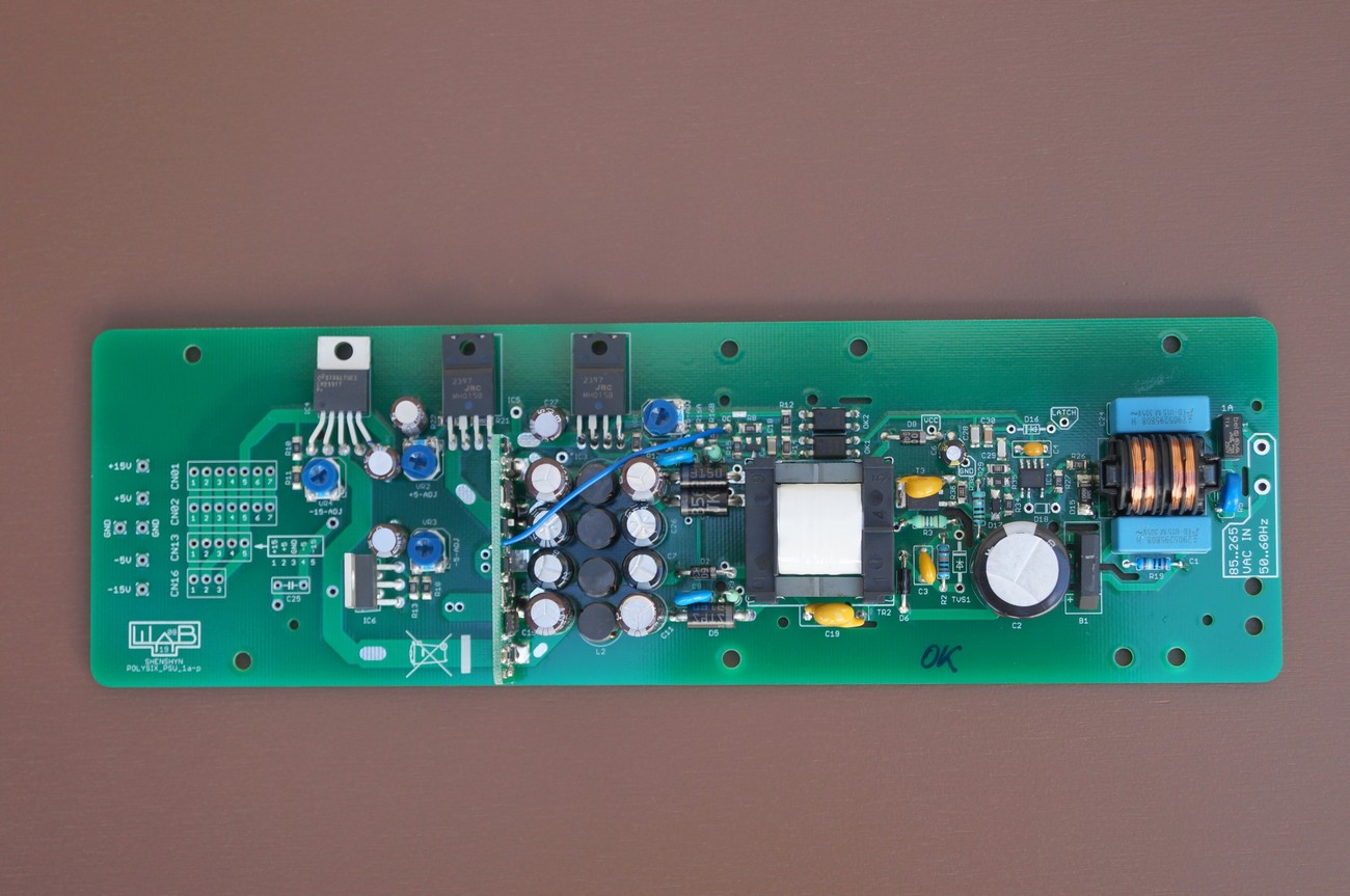
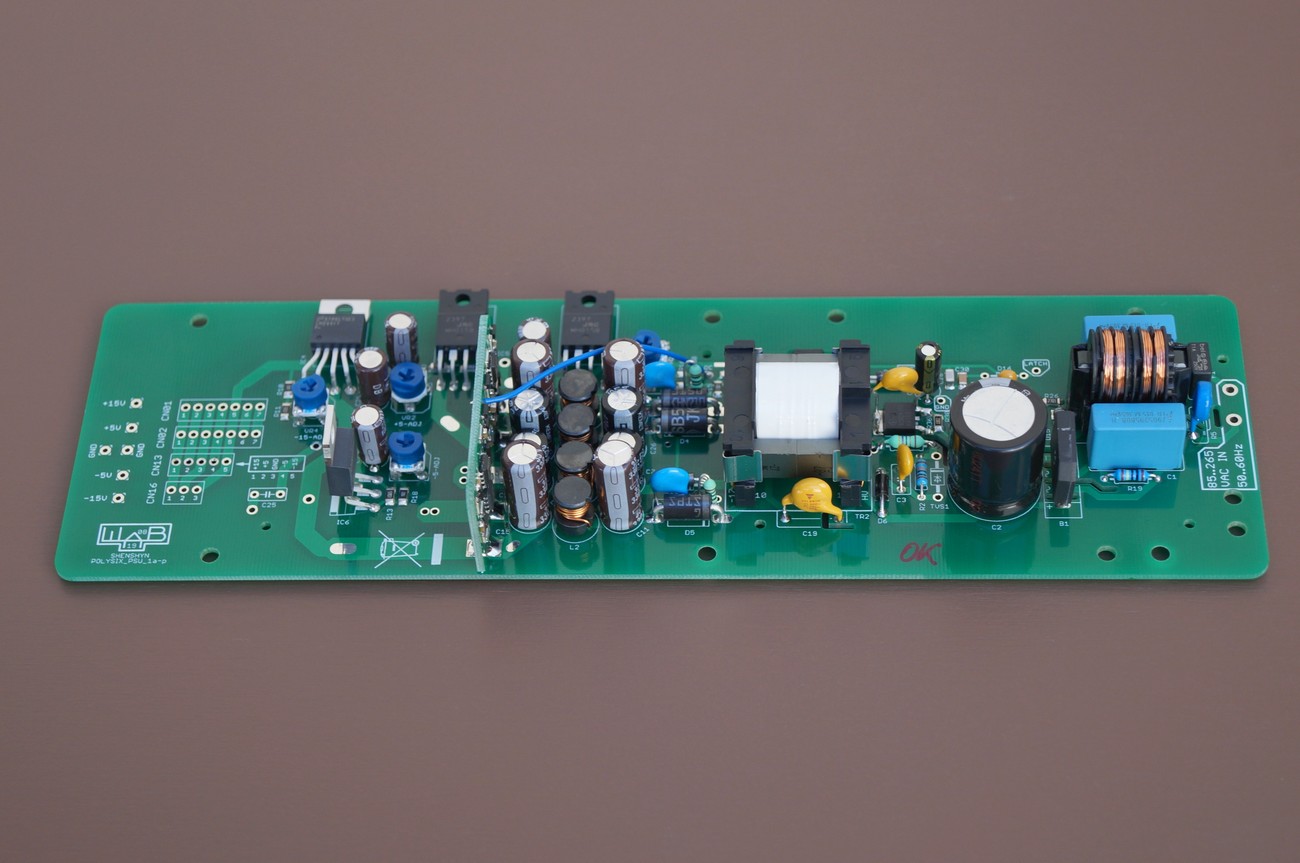
This modern and state of art PSU is suitable to replace an old PSU in Korg Polysix synthesizer. It is an universal input (85 to 265V AC) switch mode power supply (SMPS) with LDO post-regulators (on every rail).
In comparison to original PSU it has several advantages
- NO OVERHEAT! In this PSU, power components are only 15°C warmer than the ambient temperature (e.g. for ambient +20°C it is +35°C) after several hours of operation
- Efficiency around 75{eb681a58ecc476759952a50a8a7c167279151df38e58f2598760f2d2e5f4f286} = less heat inside the synthesizer
- No audible NOISE
- Precise Over Current Module that monitors possible fault conditions
- Less weight
- New and quality electronic parts
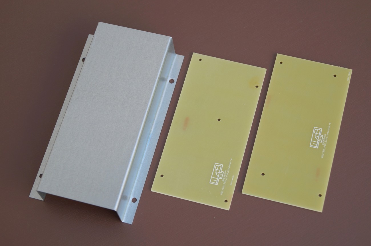
- Top metal protection cover and bottom insulator plate that covers all components under high voltage
- Compact construction
- Easy to install
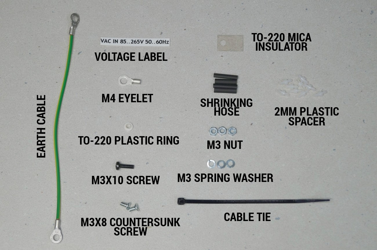
- For sale complete PSU module incl. insulator board and protection metal cover + all necessary parts to install the PSU
- Price: 190€ net
Auxiliary mounting parts
Not depicted, but will be supplied:
40 cm 2 wire cable to connect PSU and line switch/cable
yellow spacer plate
Technical information
Below block diagram of PSU is depicted. It consists of AC/DC converter, Overcurrent Protection (OCP) Module and LDO regulators
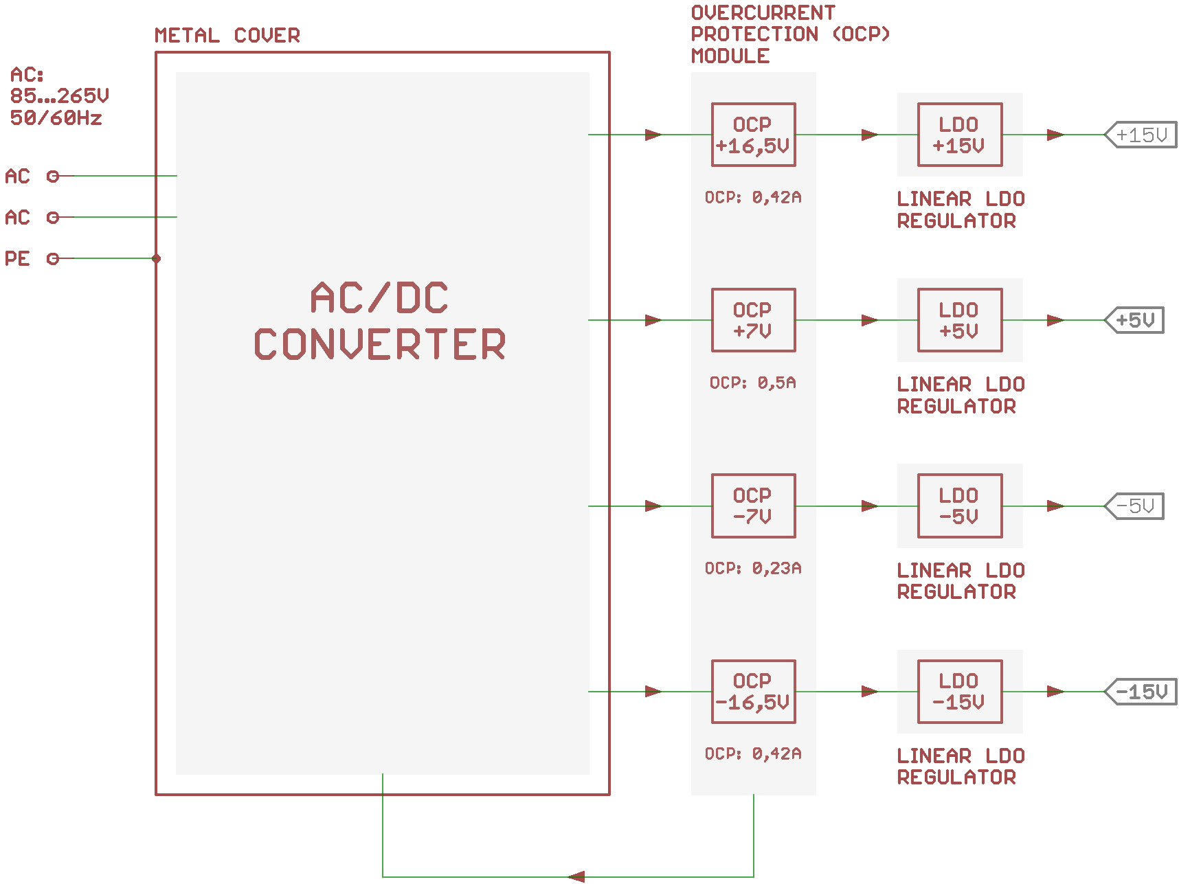
AC/DC converter
The converter has an universal 85…265VAC 50/60Hz input. It has internal over-load/temperature protection. If over-load/temperature event occurs, the AC/DC converter latches off (to be precise, it stops to switch and produce output voltages; the converter primary high voltage stage is still powered with a line voltage). Disconnecting of the PSU from the line voltage will reset the converter and if no fault condition is present it will start to work normally.
AC/DC converter uses multiple output flyback topology. The feedback senses +16,5 and -16,5 rails. Output voltages are approx. +16.5V, +7V, -7V, -16.5V that are further regulated by LDO regulators.
Overcurrent Protection (OCP) Module
Overcurrent Protection Module has precise current sensors for every rail. OCP module output is connected to the AC/DC converter controller IC. If any of following events occurs, the AC/DC converter will latch off (as described above in the „AC/DC converter“ part):
- Current on +15V rail raises to 0,42A (normal Polysix +15V rail consumption is 0,23A)
- Current on +5V rail raises to 0,5A (normal Polysix +5V rail consumption is 0,33A)
- Current on -5V rail raises to 0,23A (normal Polysix -5V rail consumption is 0,08A)
- Current on -15V rail raises to 0,42A (normal Polysix -15V rail consumption is 0,19A)
Current sensors have tolerances +-2{eb681a58ecc476759952a50a8a7c167279151df38e58f2598760f2d2e5f4f286}
Linear LDO regulators
LDO regulators in every rail regulate the AC/DC output voltages to precise +15, +5, – 5, -15V. Every regulator has its own trimpot for precise voltage adjustment.
As conclusion, this PSU has superior protection against fault conditions:
Dual OVP protection:
- LDOs in series
- controller IC OVP circuit
Double overcurrent protection:
- coarse over-current and short circuit protection as a part of controller IC circuit
- precise current sensors as a part of OCP module
Installation instructions
PLEASE NOTE! We sell a fully working and tested PSU with few additional parts to mount the PSU into the Polysix. Following installation is an example. We are not responsible for health injuries and material damages that can cause bad installation of this PSU. Only a qualified tech should make this PSU swap. You are doing the PSU swap on your own risk
DISCONNECT POWER CORD FROM THE MAINS PLUG

Remove old transformer and line filter PCB next to it
Disconnect cables from the KLM-376 voltage regulator PCB
Unscrew 4x screws on the rear of Polysix panel to dismantle the KLM-376 with it’s metal parts (one is aluminium heatsink, another is steel holder)
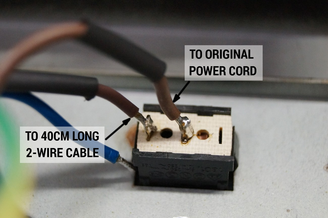
Solder line power cables as depicted
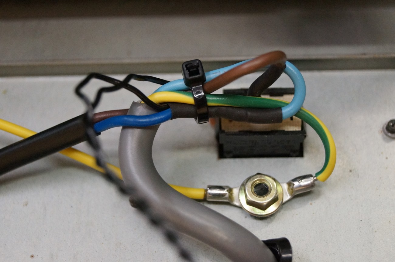
Tie tem together by means of a plastic tie
(Ignore those two thin black wires. They go to an auxiliary line transformer that is used with an MIDI mod that requires it’s own supply)

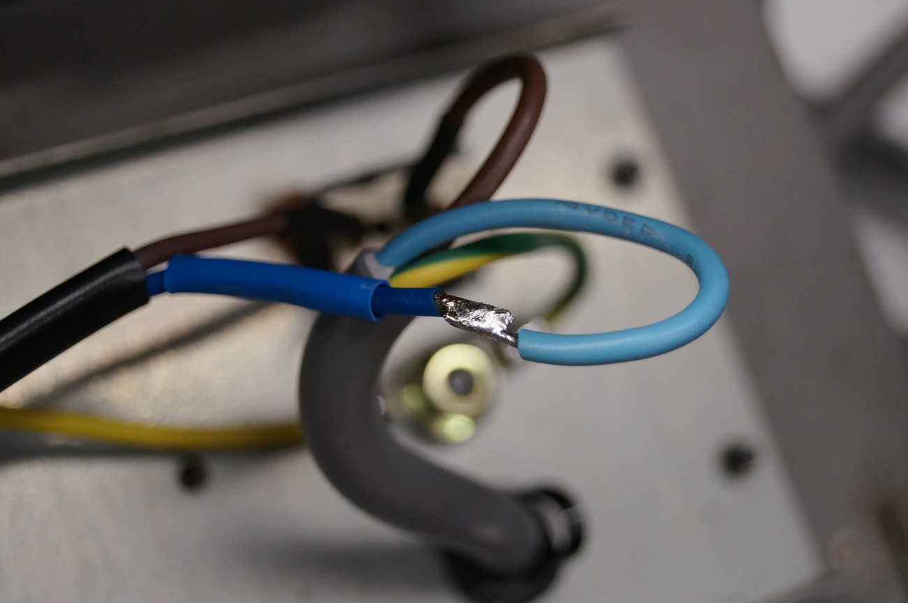
Make proper earthing connection
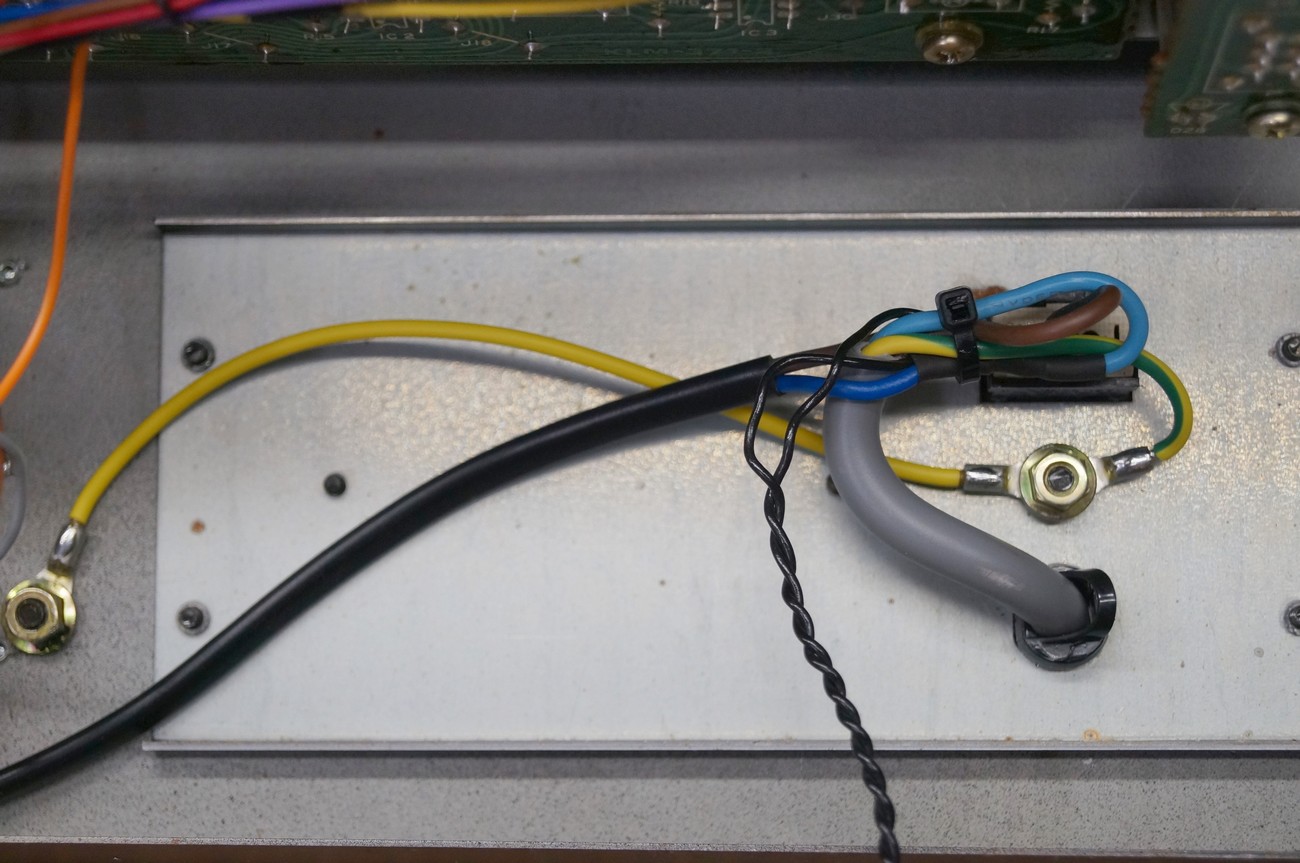
The wiring of line wires should look like this
Take a new PSU PCB and mound two insulator PCBs on it as depicted. Use 2mm plastic spacers for it
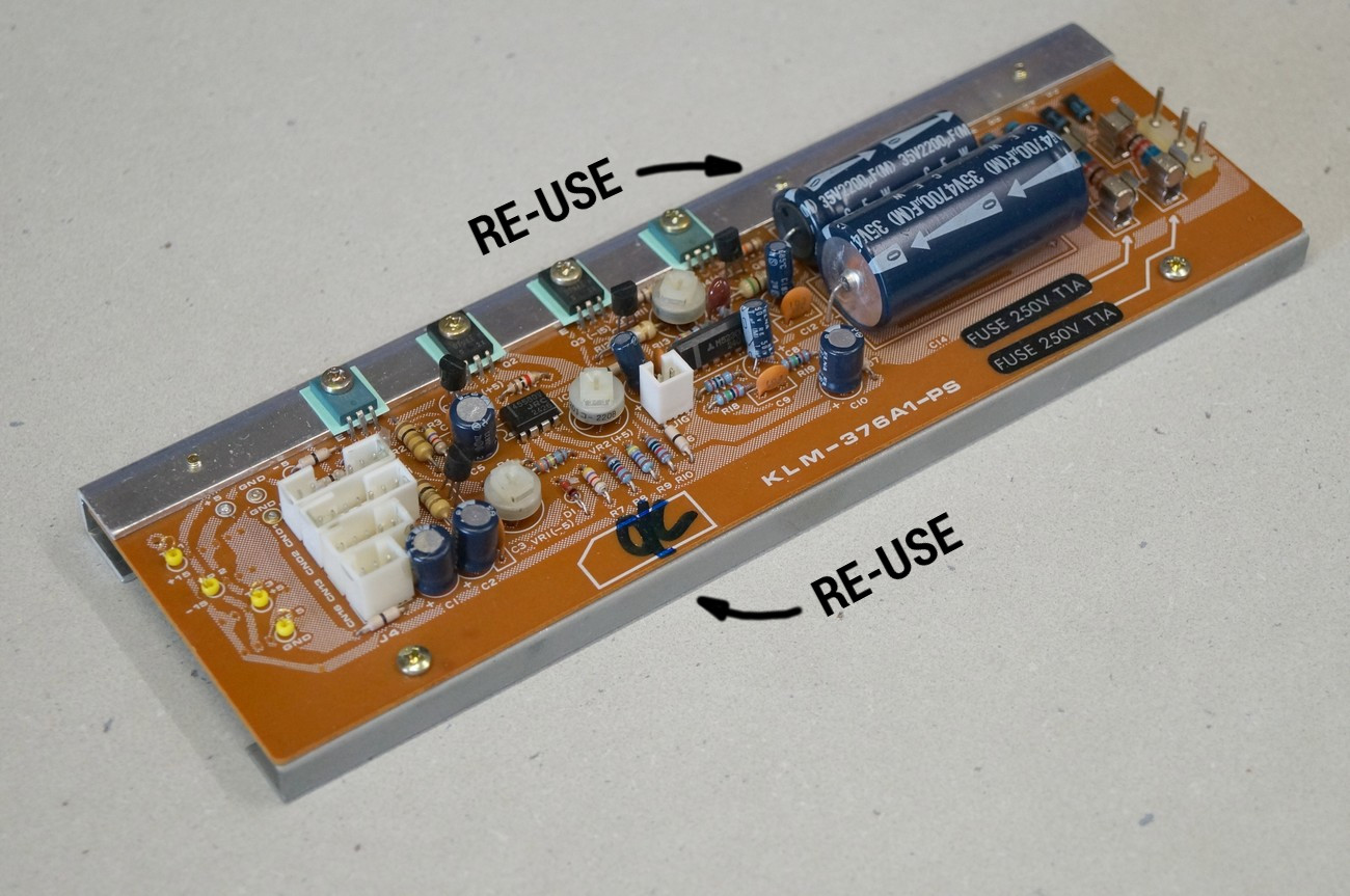
Take the old linear regulator board KLM-376. Unscrew all screws and dismantle both metal parts
De-solder original male connectors and transfer them to the new PCB

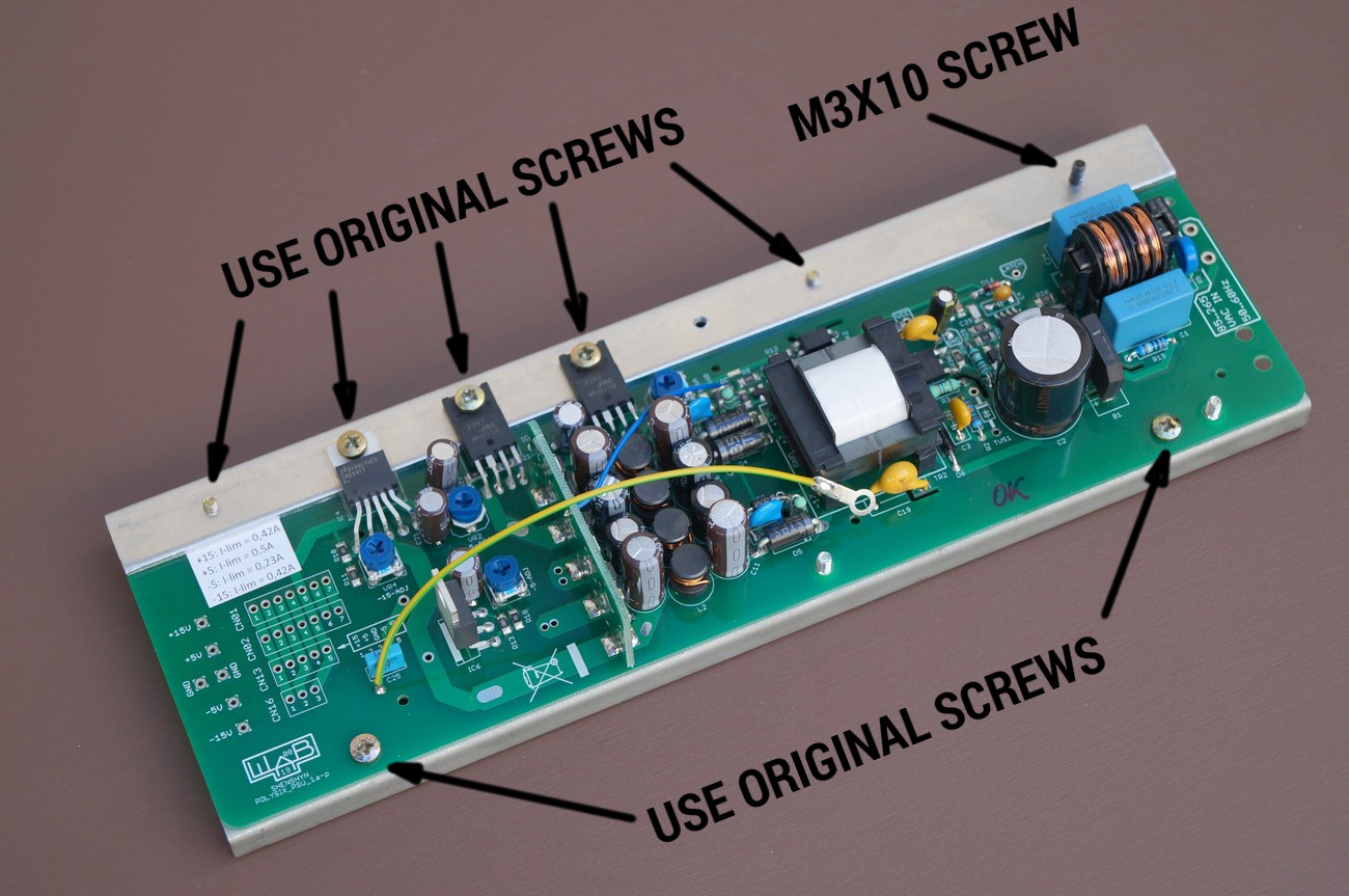
Install both metal parts on the new PCB as depicted
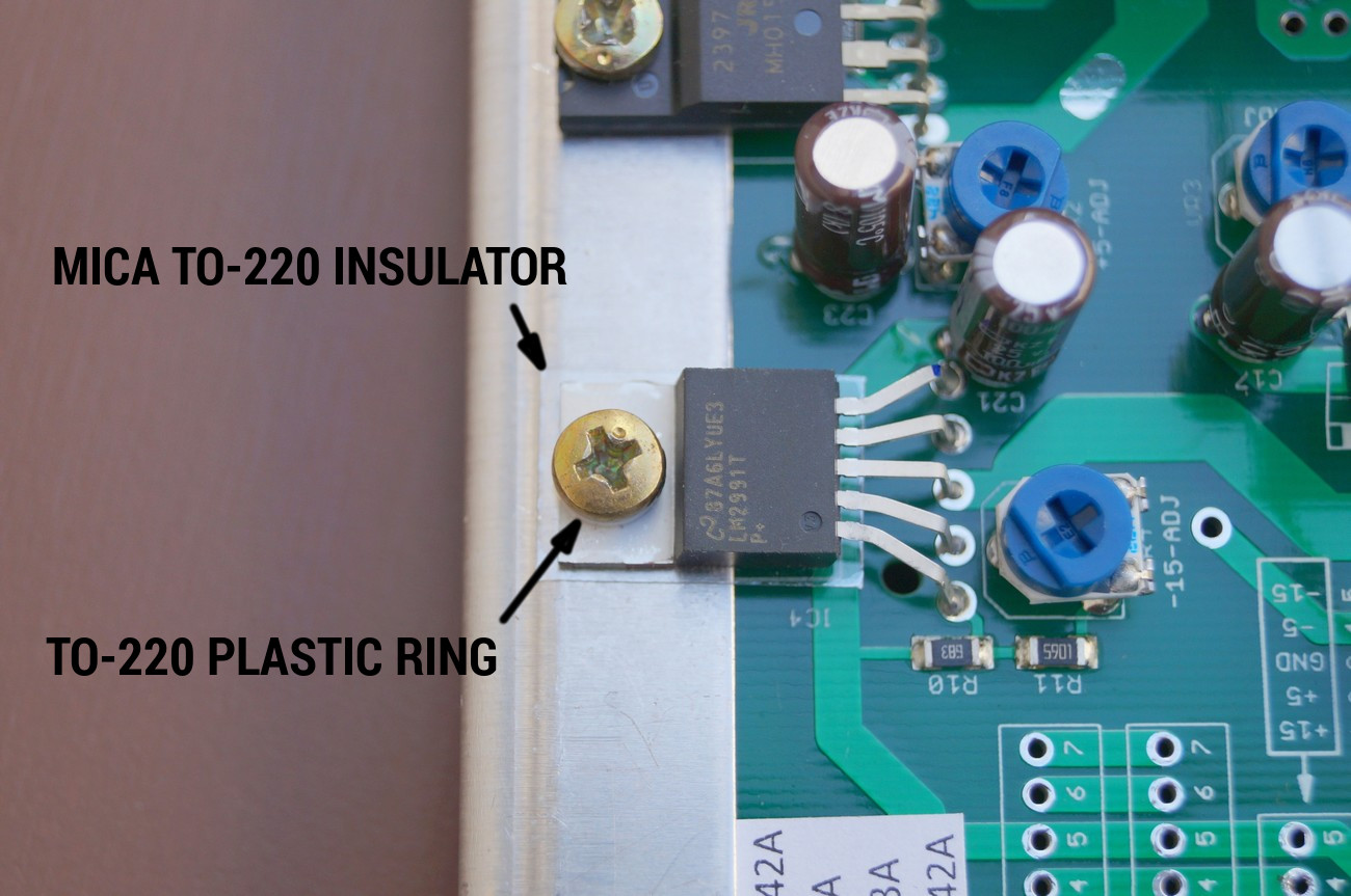
Now installing of the mica TO-220 insulator
Unpack it carefully from the paper cover
Put there the mica insulator so that both holes are CENTERED! This is very important to avoid a damaging of the insulator when installing the LDO
Use original screw and put the TO-220 insulator ring on it. Then put it into the regulator’s hole and screw carefully to the heatsink. Again, be very soft and pay attention that the mica insulator doesn’t move to the side. Otherwise it will be damaged and the metal tab of LDO will be electrically connected to the heatsink what is forbidden.
Using of heatsink paste is welcomed but not necessary due to very low dissipation on LDO regulators
Install new PSU module onto the main metal panel. Screw 4x original screws on the rear of panel
When installing the PSU, omit 2mm thick 230 x 70 aluminium plate
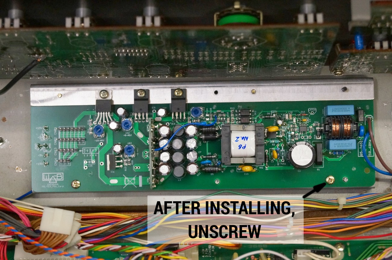
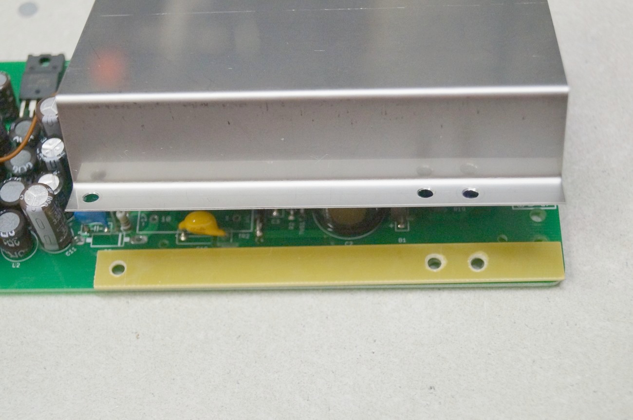
Unscrew marked screw. It will be screwed back after placing of metal cover

Solder both wires of the 40cm line cable. Solder joint should be strong and clean without any metal residues
Place yellow spacer plate between PCB and metal cover
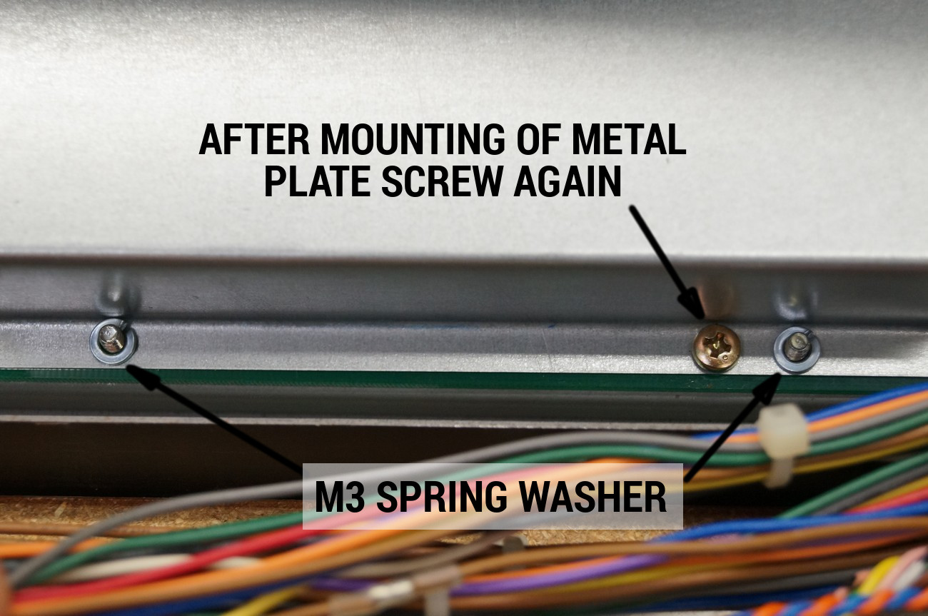
Place metal cover on the PSU PCB and mount the original screw again
Put M3 spring washer on every thread of the screw and then fasten with M3 nut
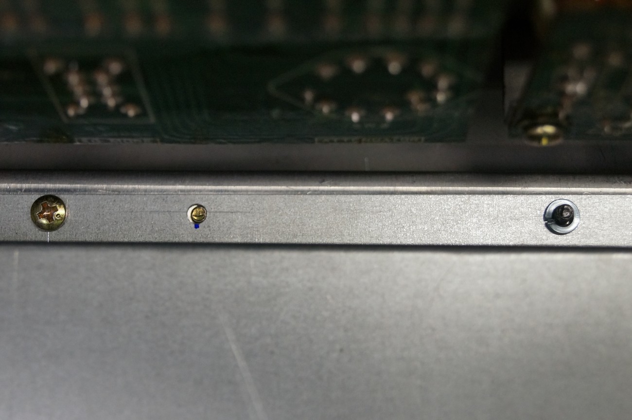
The same for the top side of the metal cover
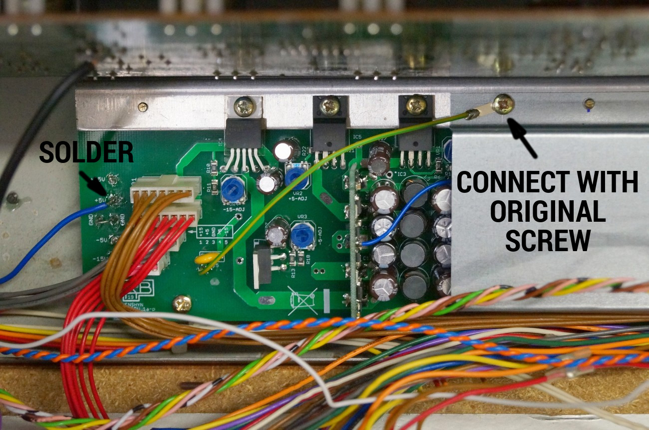
When installing top original screw, also fasten an earthing cable as depicted
Now it should look like this

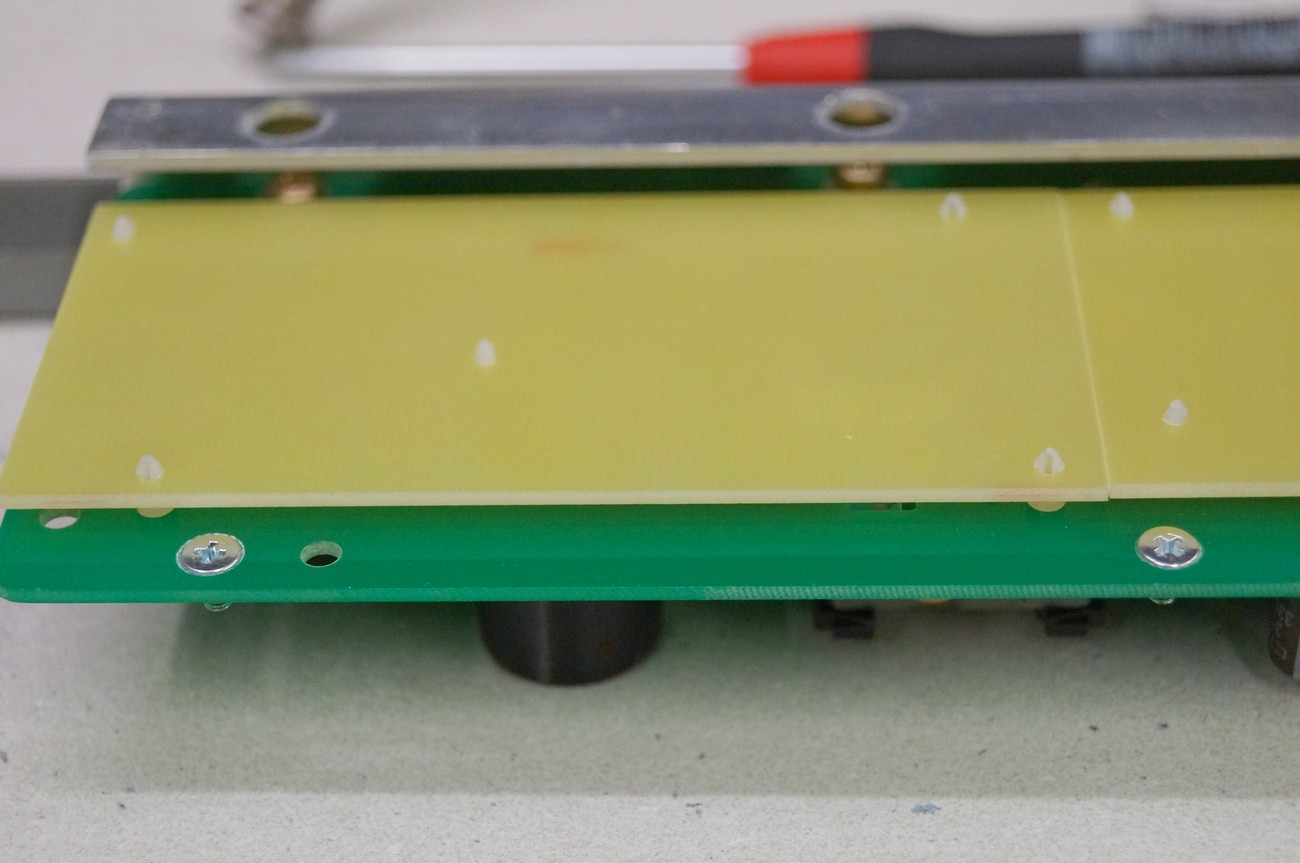
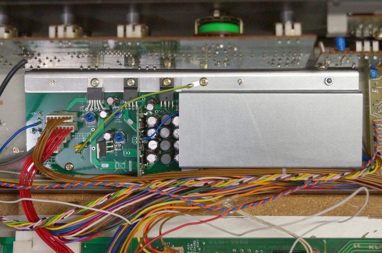
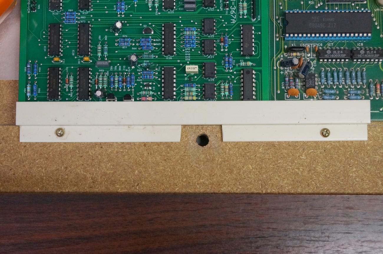
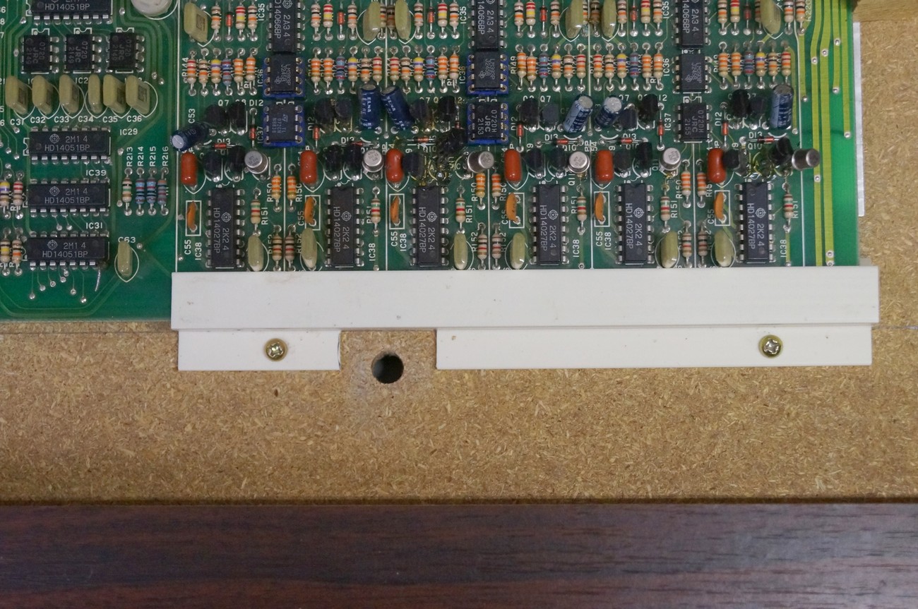
The PSU replacement is slightly higher then original KLM-376 board because of the metal cover. When putting the main metal panel down, it may hit KLM-367 and KLM366 PCBs. That’s why it is necessary to move these PCBs approx 10 mm in direction of keyboard.
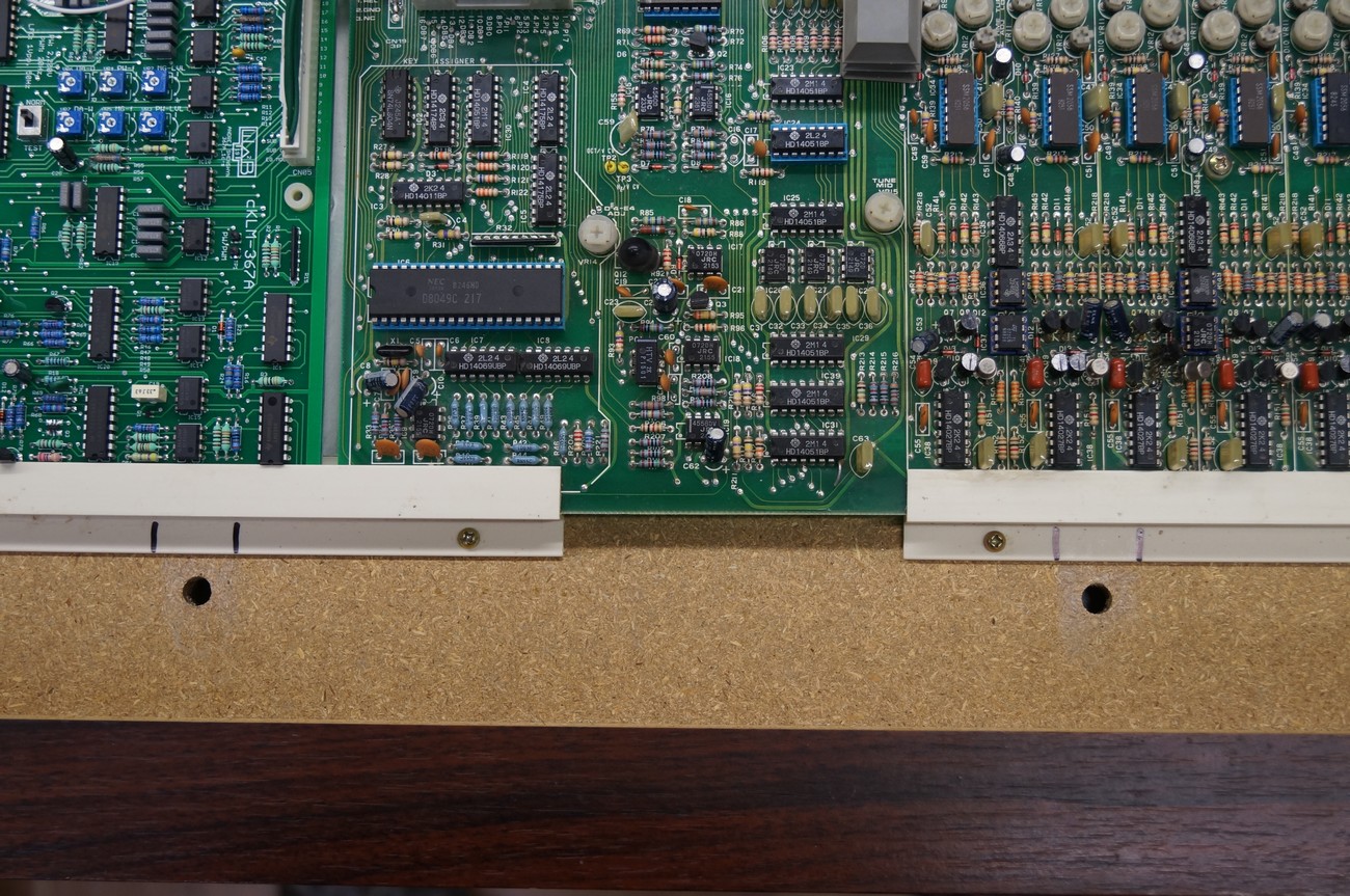
Mark plastic PCB holders as depicted. The space between two markings will be cut out to permit keyboard metal holders to move into cut out space.
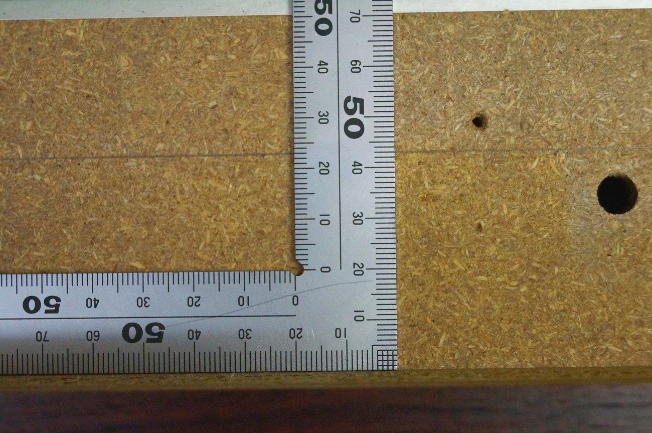
Distance between the vertical edge of PCB holder and the edge of chassis is 43mm
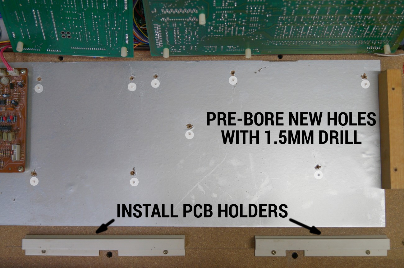
Install at first PCB holders and then place PCBs onto the chassis and press them in direction keyboard so that they move as deep as possible into PCB holders. Then pre-drill new holes, de-install PCBs, clean everything and re-install and screw to chassis.

Mark universal input with a label. Cover original voltage rating to avoid confusion
Before connecting of +5, -5, +15, -15 connectors to synth boards, check the PSU voltages with scope or DVM. If everything is OK plug the connectors
READY!
Some safety recommendations when working with the PSU
- Be careful, the big bulk electrolytic cap is still charged with high voltage (for 115VAC it is 165V and for 230VAC it is 330V) after the PSU was turned or latched off
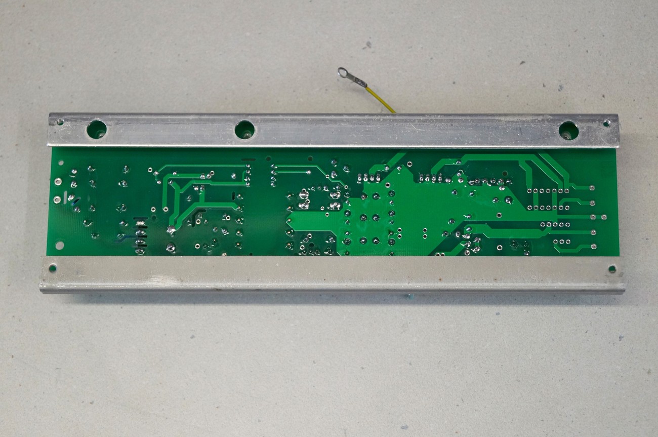
- When de-installing the PSU, short + and – terminals of the bulk cap (bottom side of the PCB) with a 470 ohm / 5W resistor for 1 second. At this time, PSU should be disconnected from the line voltage
- Line voltages in the Polysix are still present, even if switch is turned off (only 1 pole switch is used)! Be careful with line wires!